

You are here
Back to topHow to Choose Heat Sink?
Temperature has a decisive impact on the lifetime, reliability, and performance of electronic products. Effective thermal management strategies not only ensure stable operation of devices under high ambient temperatures but also help maintain superior electrical performance and energy efficiency.
This article focuses on one of the most commonly used passive cooling technologies in converter applications—the heat sink. It explains the basic operating principles of heat sinks and discusses key factors to consider when selecting an appropriate one, such as thermal conductivity of the material, geometric design, surface treatment, and mounting method. The goal is to provide users with a comprehensive evaluation framework to help them choose the most suitable heat sink solution based on their specific application requirements.
Introduction
The thermal performance of electronic products is a key indicator that affects overall system performance and stability. Currently, common thermal management techniques can be broadly categorized into two types: active cooling and passive cooling. Active cooling relies on externally devices to enhance heat conduction and convection, with common methods including liquid cooling and air cooling.
Liquid cooling dissipates heat by installing a water block or cold plate on the heat-generating components. A coolant circulates through pipes, transferring heat from the source to a cooling system (such as a chiller) where heat exchange occurs. The cooled liquid is then recirculated for continuous use. While this method offers extremely high cooling efficiency, it also comes with higher system costs and installation complexity. Therefore, it is primarily used in high-power equipment such as servers and high-end computer CPUs.
Air cooling, on the other hand, enhances heat convection by using fans to increase airflow, quickly expelling heat from the source. To improve thermal performance, air cooling systems are often combined with heat sinks (as shown in Figure 1), which increase the effective surface area for heat exchange. This method is suitable for medium to low-power applications or space-constrained environments.

In contrast, passive cooling does not require any external devices. Instead, it relies on heat conduction in combination with natural convection or radiation to dissipate heat. The most common approach involves the use of a heat sink, which transfers heat from the source to its fins and then releases it into the surrounding environment through natural airflow.
This article provides an in-depth analysis and discussion of the heat sink.
Heat Sink: Principles and Overview
1. Characteristics of Heat Sink
The heat sink is a widely used passive cooling component in power electronic devices, and its performance is influenced by factors such as material, surface design, total surface area, and geometric structure.
A. Heat Sink Material
The thermal conductivity of common heat sink materials available on the market is compared in Table 1.
| Material | Thermal Conductivity (W/mK) |
| Copper | 401 |
| Pure Aluminum | 237 |
| Aluminum Alloy | 100~200 |
| Silver | 420 |
| Gold | 381 |
| Steel | 60 |
The thermal conductivity of aluminum can be further categorized into pure aluminum and aluminum alloys. Pure aluminum has a thermal conductivity of approximately 237 W/m·K, while aluminum alloys typically range from 100 to 200 W/m·K, depending on the specific alloy grade. Pure copper has a thermal conductivity of approximately 401 W/m·K. As shown in Table 1, silver has slightly higher thermal conductivity than copper; however, due to its high cost, it is rarely used as a heat sink material in practical applications. In contrast, aluminum alloys offer advantages such as low cost, light weight, and good machinability, making them the most commonly used material for heat sinks.
According to Fourier’s law of heat conduction, the rate of heat conduction can be expressed as: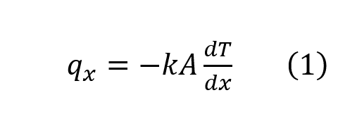
Where qx
is the heat flux (heat conduction power), k is the thermal conductivity, A is the heat transfer area, andThis relationship shows that, under the same cross-sectional area and temperature gradient, a material with higher thermal conductivity provides better heat conduction capability. However, the actual thermal performance of a heat sink also depends on other factors, including fin geometry, surface area, airflow conditions, contact thermal resistance, and the mounting method.
B.Heat Sink Structure
The design of the physical structure also has a significant impact on cooling performance. From equation 1, it can be seen that heat flux is directly proportional to the surface area of the heat sink. Besides the surface area, the thickness and the physical design of the fins also affect both heat conduction and convective efficiency.
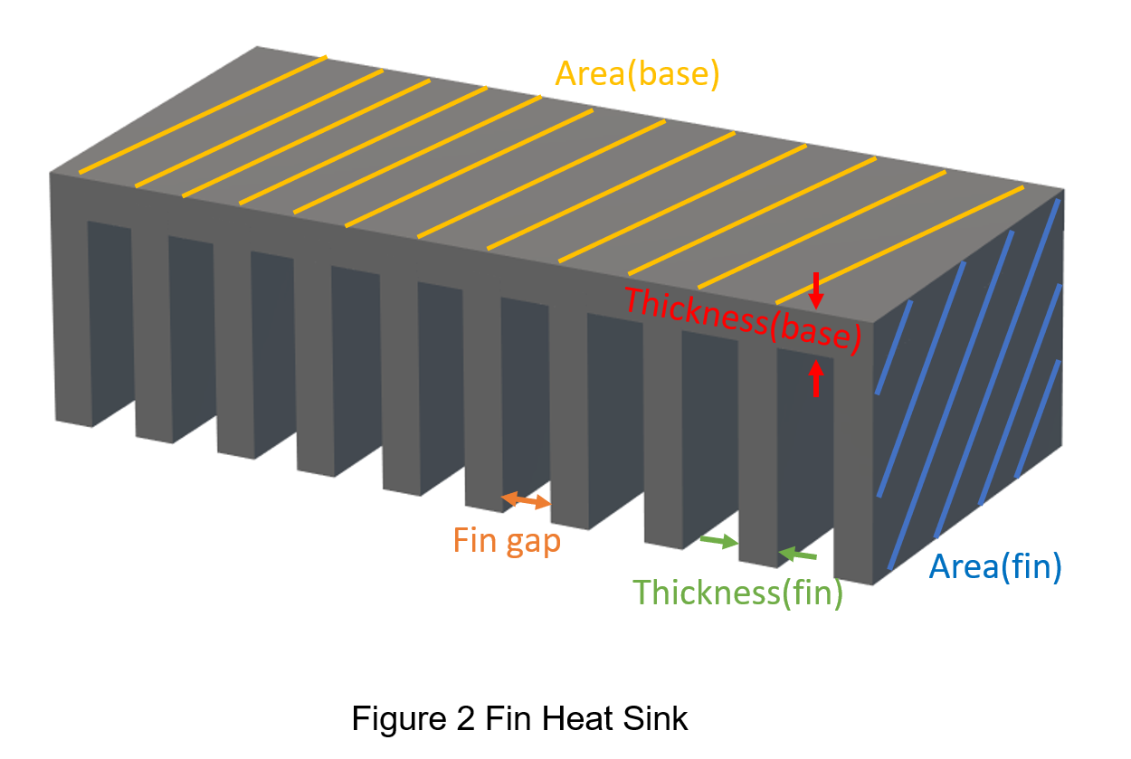
Taking the most common fin heat sink as an example, as shown in Figure 2:
- Heat sink base surface area (yellow area): A larger base area provides a greater contact area with the heat source or thermal interface material, helping to reduce contact thermal resistance.
- Heat sink base thickness (red area): The base thickness must be optimized between heat spreading and conduction path length. A base that is too thin may cause localized hot spots, while an overly thick base can increase thermal resistance, weight, and material cost. Therefore, the thickness should be optimized based on the heat source power and mounting conditions.
- Fin surface area (blue area): A larger fin surface area increases the contact area with the surrounding air, improving convective heat transfer and helping dissipate heat more effectively into the ambient environment.
- Fin thickness (green area): Fin thickness affects heat conduction, mechanical strength, and the number of fins that can be arranged within a given space. Fins that are too thick reduce the number of fins and the effective surface area per unit volume, while fins that are too thin may have insufficient heat conduction capability or reduced structural strength.
Fin gap (orange area): Fin spacing should be designed according to natural convection or forced-air cooling conditions. Excessive spacing reduces the available surface area per unit volume, while insufficient spacing increases airflow resistance, restricts air circulation, and reduces cooling efficiency.
In addition to finned heat sinks, common heat sink designs also include pin-fin heat sinks and plate-fin heat sinks. A pin-fin heat sink has a structure similar to a finned heat sink, with heat-dissipating pins extending upward from a base. Although each individual pin has a relatively small surface area, the pin-fin structure reduces airflow direction constraints and allows airflow from multiple directions. This makes it suitable for compact designs or applications with limited space and uncertain airflow direction, such as small power modules.
A plate-fin heat sink is typically constructed with parallel metal plates arranged at fixed spacing, providing a large heat dissipation surface area and stable airflow channels. This type of design is commonly used in high-power-density applications or systems that require forced-air cooling, such as industrial power supplies, server power systems, and other high-performance thermal management solutions.
2. Thermal Resistance and Selection Guidelines for Heat Sinks
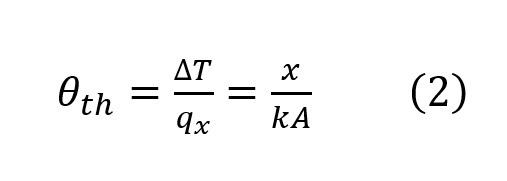
In addition to heat sink material and mechanical structure, selecting an appropriate heat sink also requires evaluating the overall thermal resistance. Based on Fourier’s law of heat conduction, the conduction thermal resistance can be expressed as:
Where![]() is the thermal resistance,
is the thermal resistance, 
![]() is the temperature difference, and
is the temperature difference, and ![]() represents the heat transfer path. This equation shows that, under the same material and cross-sectional area, a longer heat conduction path results in higher thermal resistance. Therefore, heat sink design should minimize the heat conduction path and increase the effective conduction area whenever possible. After understanding the basic definition of thermal resistance, practical applications can be used to calculate the thermal resistance of a cooling system and select a suitable heat sink.
represents the heat transfer path. This equation shows that, under the same material and cross-sectional area, a longer heat conduction path results in higher thermal resistance. Therefore, heat sink design should minimize the heat conduction path and increase the effective conduction area whenever possible. After understanding the basic definition of thermal resistance, practical applications can be used to calculate the thermal resistance of a cooling system and select a suitable heat sink.
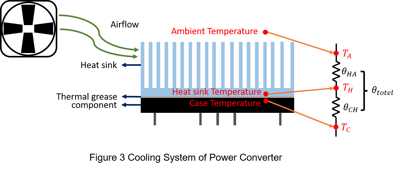
Taking a power converter application as an example, as shown in Figure 3, a thermal interface material (TIM) is typically applied between the converter and the heat sink, such as thermal grease, thermally conductive adhesive, or a thermal pad. The primary function of the TIM is to fill microscopic air gaps at the contact interface and reduce contact thermal resistance, allowing heat to transfer more effectively from the power module to the heat sink.
The heat conduction power in equation 2 can be considered as the power loss of the converter, and therefore the equation can be rewritten as follows:
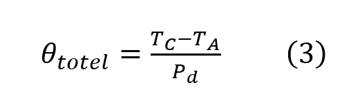
Where ![]() is the total thermal resistance, TC is the case temperature of the converter, TA is the ambient temperature, and
is the total thermal resistance, TC is the case temperature of the converter, TA is the ambient temperature, and  Pd is the power loss of the converter.
Before selecting a heat sink, it's necessary to determine the converter’s case temperature and power loss, then set a target ambient temperature. With these values, the total thermal resistance can be calculated using equation 3, which can then be used as a basis for choosing an appropriate heat sink.
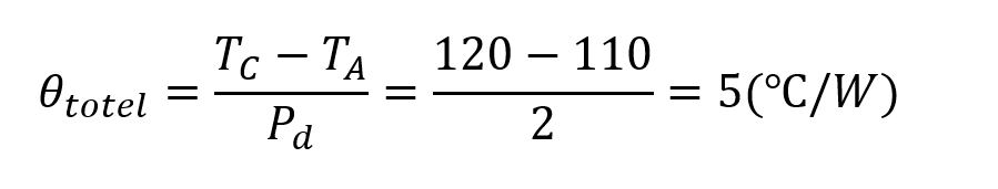
For example, suppose a converter has a power loss Pd=2W , a case temperature TC=120 °C
 , and we aim to maintain an ambient temperature TA=110 °C. The total thermal resistance can be calculated as follows:
The thermal resistances between different temperature points along the same heat dissipation path can be connected in series to obtain the total thermal resistance, as shown in equation 4:
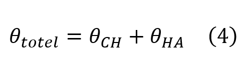
We have already calculated the total thermal resistance to be 5(°C/W). Now, we will calculate the thermal resistance from the case to the heat sink and the thermal resistance from the heat sink to the ambient environment.
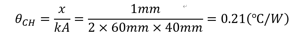
Since there is TIM between the converter case and the heat sink, assume it is thermal grease with a thermal conductivity of K=2W/mK. The applied area is 60mm x 40mm, and the thickness is 1mm.
The thermal resistance from the case to the heat sink ![]() can be calculated as:
can be calculated as:
The thermal resistance from the heat sink to the ambient ![]() :
:
![]()
From the above calculation, it can be concluded that in order to select a suitable heat sink for this converter, the heat sink must have a thermal resistance less than  4.79(°C/W) . If a cooling fan is added, then the combined thermal resistance of the heat sink and fan must also be less than 4.79(°C/W).
Conclusion
Heat sinks are commonly used and essential thermal management components in power converters. A clear understanding of material selection, mechanical design, and thermal resistance calculation helps improve system thermal performance and long-term reliability.
This article explains the key factors that affect heat sink performance, including material thermal conductivity, mechanical dimensions, surface area, thickness, and common heat sink structures. Through formula derivation and practical examples, it provides a design evaluation process for selecting an appropriate heat sink based on power dissipation, ambient temperature, and thermal resistance requirements, helping reduce the operating temperature of power converters and improve overall system stability.
CTC is service provider for high-end power modules (DC to DC Converter and AC to DC Converter) for critical applications worldwide since 1987. We aim to be business generator and a virtual business unit. CTC is your own team with 35 years of experience for a strong business program from market research, product definition & development, supply chain management and total technical services.
CTC is the only corporation certificated with ISO-9001, IATF-16949, ISO22613(IRIS), and ESD/ANSI-2020. We can 100% ensure not only the product, but also our workflow and service to match quality management system for every high-end application from the very beginning. From design to manufacturing and technical support, every single detail is operated under highest standard.