

You are here
Back to topReverse Current Protection
MOSFETs are often used as switches in power systems nowadays, but the presence of MOSFET body diodes cannot prevent reverse current when the MOSFET is in the off state. If the circuit is not properly protected, it will lead to extra energy loss. This article will discuss common reverse current protection methods and compare the differences, so that users can find a suitable protection scheme according to different circuit requirements.
1. Introduction
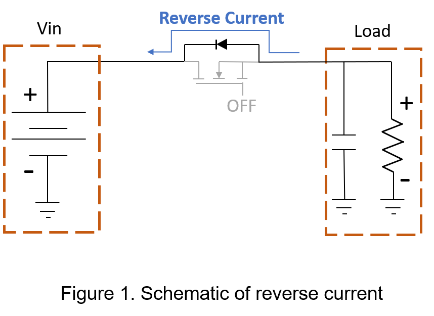
When the current direction of the system is opposite to the direction of normal operation, it is called reverse current. The current direction marked in Figure 1 is the reverse current flowing through the body diode of the MOSFET. The causes include reverse battery connection, multiplexing application, car startup process and so on. For example, in a battery application system, a reverse current will be generated if the positive and negative electrodes of the battery are reversely connected.
2. Protection Mode
Reverse current causes damage to the sensitive components in the circuit, such as low-withstand-voltage capacitors, LEDs. Therefore, the reverse current is needed to less or even blocked. The following describes the protection methods to reduce reverse current.
- Diode
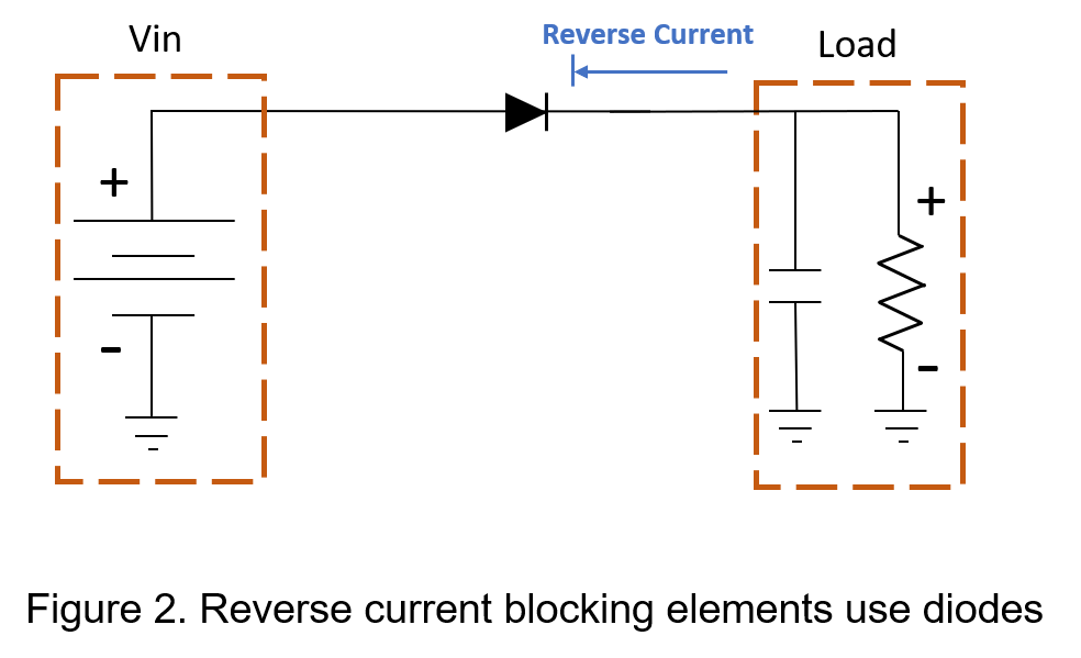
Using diodes as reverse current protection is a very simple and reliable solution that is low cost and easy to be integrated, as shown in Figure 2. But in battery applications, the forward voltage drop across the diodes will shorten battery life and reduce conversion efficiency.
For example, a conventional diode has a voltage drop of 0.7V across the diode, and if the system current is 5A, the diode itself will incur 0.7V×5A=3.5W losses. In order to reduce the loss and pressure drop problems caused by the diode, Schottky diode with lower voltage drop can be used, but the cost is higher and has a larger reverse leakage current.
- Back-to-Back MOSFETs
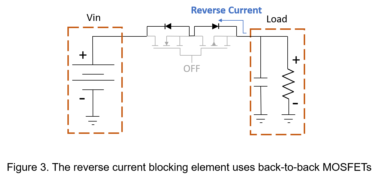
MOSFETs are often used as switching assemblies in circuits. Because body diode of a single MOSFET cannot be protected against reverse current surges, use another MOSFET with the opposite direction of drain and source in series can effectively be protection against reverse current, as shown in Figure 3.
This method has the characteristics of low positive conduction voltage and allowed high current, which is more correspond to the need for low power loss than diodes, but requires a larger circuit board area.
3. Extended Application
- Load Switch
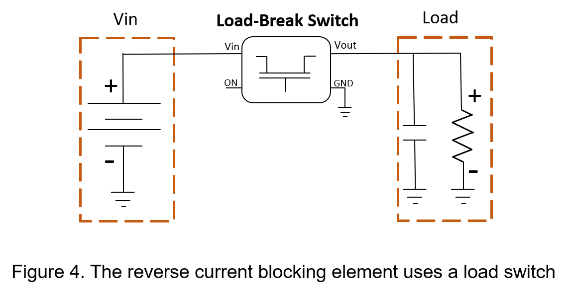
The function of the load switch is to turn on and off the electronic relay. The common pins of load switch are input voltage, output voltage, remote control signal and ground. Figure 4 shows a load switch with a reverse current blocking function, and internal circuit is to use MOSFET or diode to achieve reverse current protection.
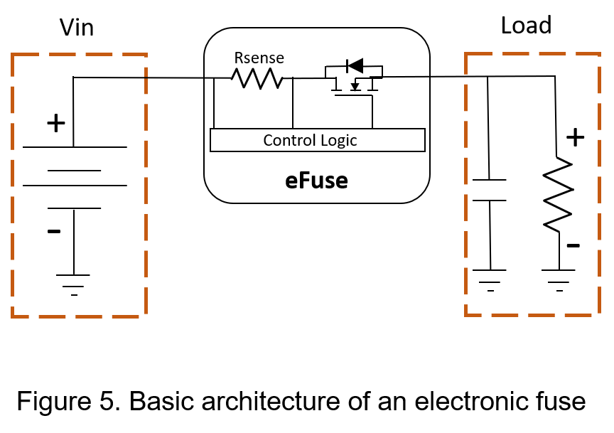
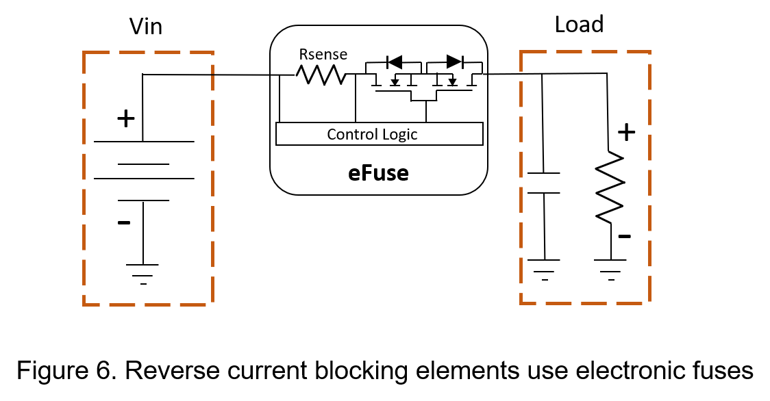
- Electronic Fuses
Electronic fuses are new type fuses that extend from traditional temperature fuses, as Figure 5, the principle is that the current supplied to the load will flow through the MOSFET and the sensing resistor. Through the voltage monitoring on the sense resistor, if the voltage across the sense resistor exceeds a preset value, the control logic will turn off MOSFET to achieve protection. Most electronic fuses with reverse current protection use back-to-back MOSFET to achieve protection functions, as shown in Figure 6.
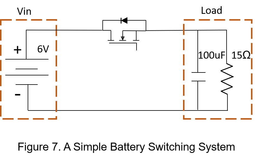
4. Battery switch circuit experiment
Common reverse current protection is extended by diodes and MOSFETs. Taking diodes and MOSFETs as experimental objects, a simple battery switches circuit observe the voltage and current as the reverse current occurs, and the component specifications are Figure 7.
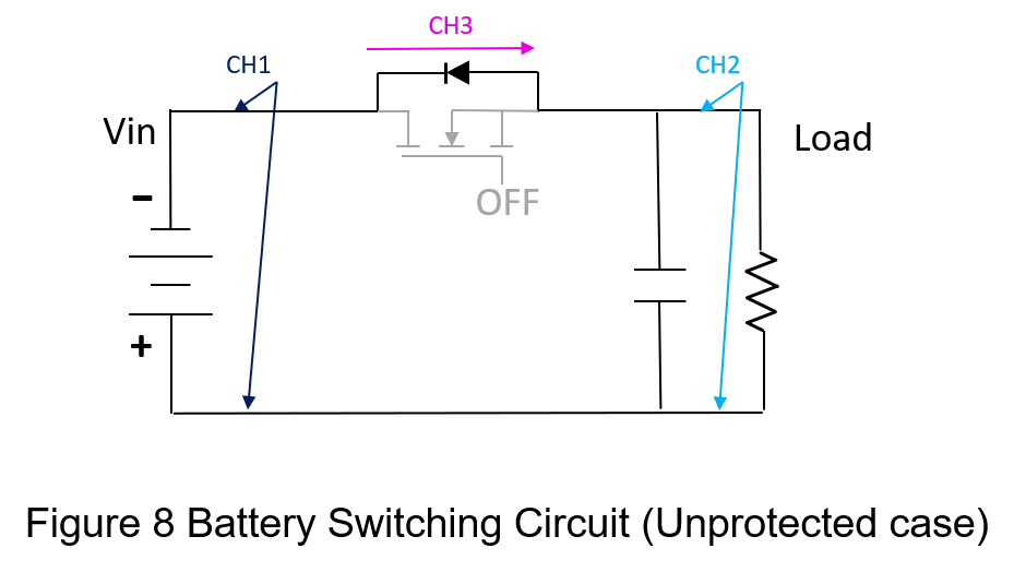
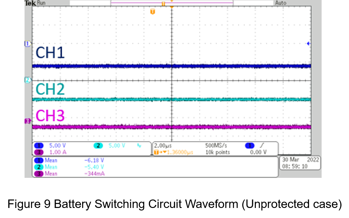
- Unprotected
The circuit architecture is shown in Figure 8 with a reverse 6V battery on the power supply terminal and a MOSFET state is off. In Figure 9, CH1 is the input voltage, CH2 is the output voltage, and CH3 is the reverse current. The output voltage is due to the body diode of the MOSFET. It drops by 0.78V and the current is -344mA, which is roughly equal to that the value of 5.4V/15 Ω. It can be seen that the switching circuit will not be able to suppress the reverse current without protection measures, and will produce greater harm in systems.
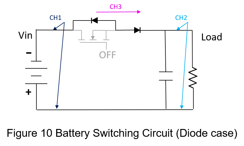
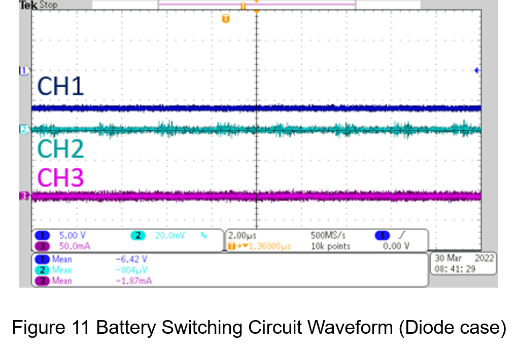
- Diode
Based on the circuit in Figure 8, the series diodes are shown in Figure 10 and the voltage and current measurement results shown in Figure 11, where CH1 is the input voltage, CH2 is the output voltage, and CH3 is the reverse current. It can be seen that the reverse the current is effectively suppressed in -1.87mA. Although diodes can lower reverse current, it will be affected by the barrier voltage in normal operation, reducing the output voltage and shortening the battery life.
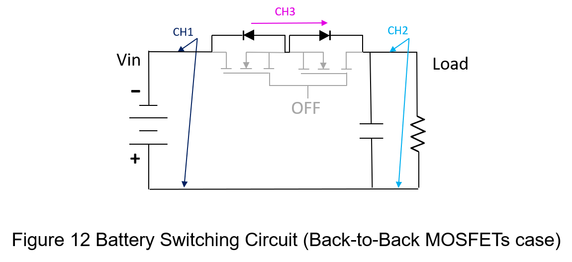
- MOSFET
Figure 12 is a schematic of a circuit for replacing diodes with back-to-back connection of N-MOSFETs that are more suitable for high-current applications than diodes. The voltage and current measurement results are shown in Figure 13, where CH1 is the input voltage, CH2 is the output voltage, and CH3 is the reverse current. It can be seen that the reverse current is effectively suppressed, only -1.54mA.
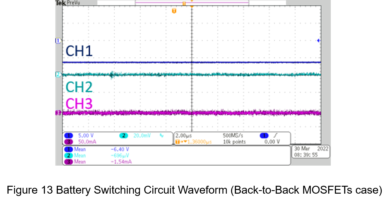
The data summarized in Table 1.
| Unprotected | Diode | Back-to-Back MOSFETs | |
| Input Voltage | -6.18V | -6.42V | -6.40V |
| Output Voltage | -5.40V | -804uV | -696uV |
| System Current | -344mA | -1.87mA | -1.54mA |
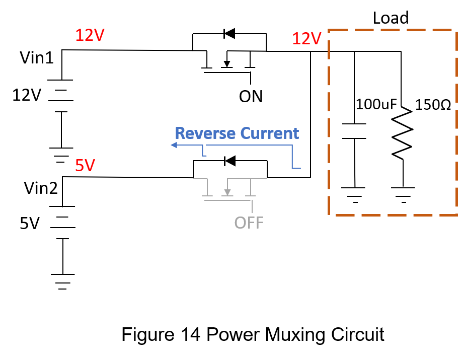
5. Multiplexing Circuit Experiments
If the circuit has no reverse current protection for multiplexing case, it will cause the current to flow back to the power supply and then damage the system. The circuit and component specifications are shown in Figure 14. In the following, diodes and MOSFETs are used as experimental objects to observe the use of different components in the reverse direction. The voltage and current changes when reverse current occurs.
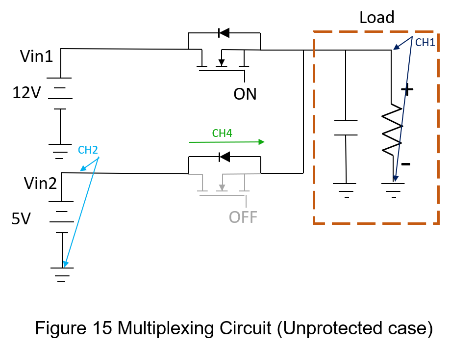
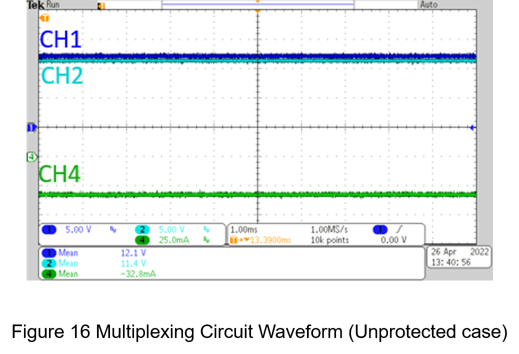
- Unprotected
The circuit architecture is shown in Figure 15. The MOSFET status of on for Vin1 and other MOSFET status of off for Vin2, The voltage and current measurement results are shown in Figure 16, where CH1 is the load-side voltage, CH2 is the input voltage of Vin2, and CH4 is the input current of Vin2. In Figure 16, It can be seen the voltage of Vin2 rises from 5V to 11.4V, which is caused by the current of Vin1 returning to Vin2 through the lower MOSFET, and then the current of CH4 is -32.8mA, Therefore, the reverse current will impact the low-voltage power supply with no protection measures.
- Diode
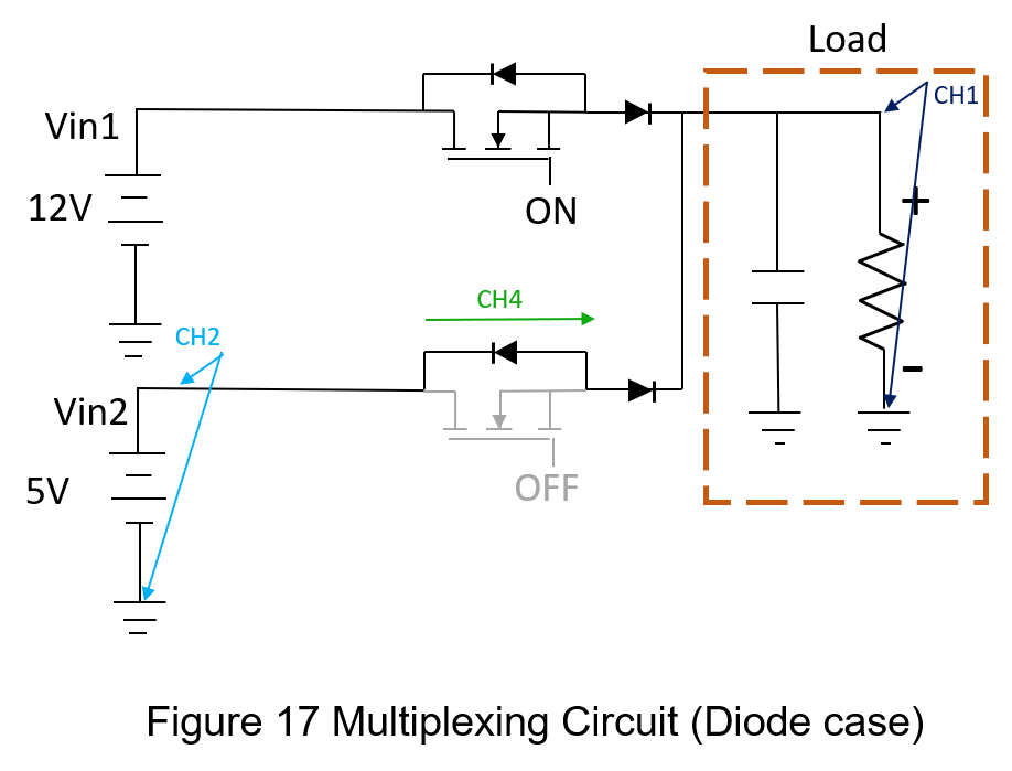
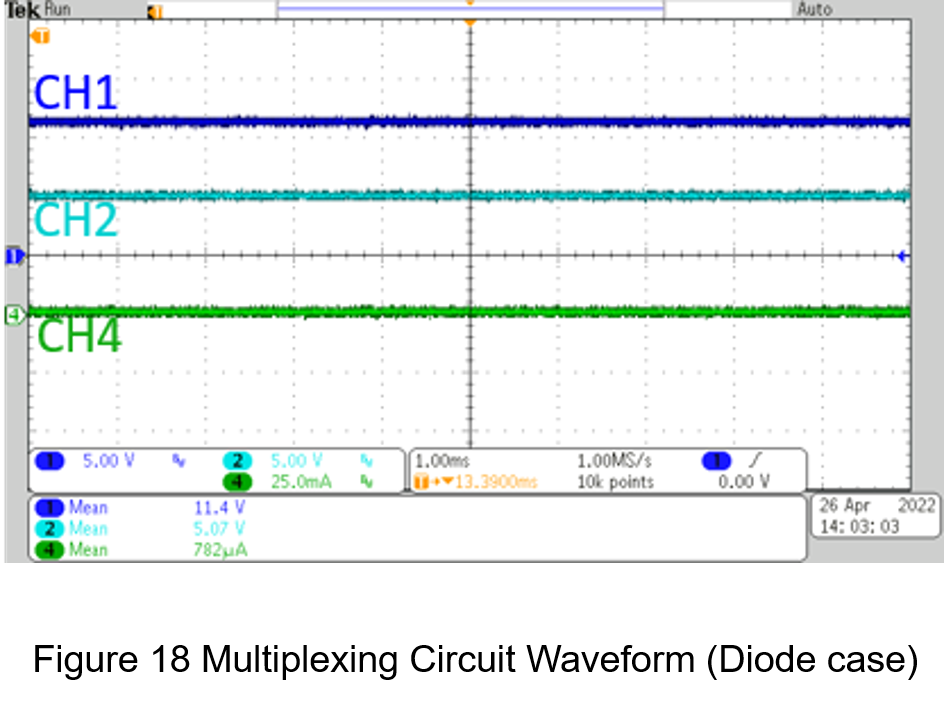
On the basis of the circuit in Figure 15, both MOSFETs are connected in series with diodes as shown in Figure 17. The voltage and current measurement results are shown in Figure 18. It can be seen the reverse current is effectively suppressed.
- Back-to-Back MOSFETs
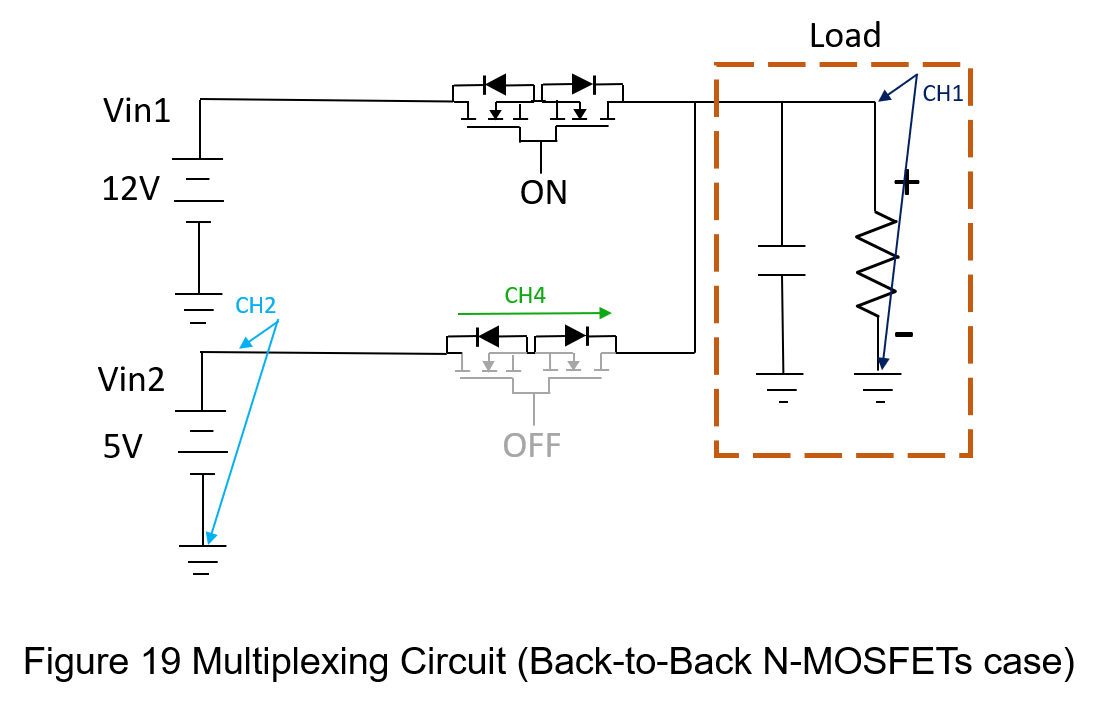
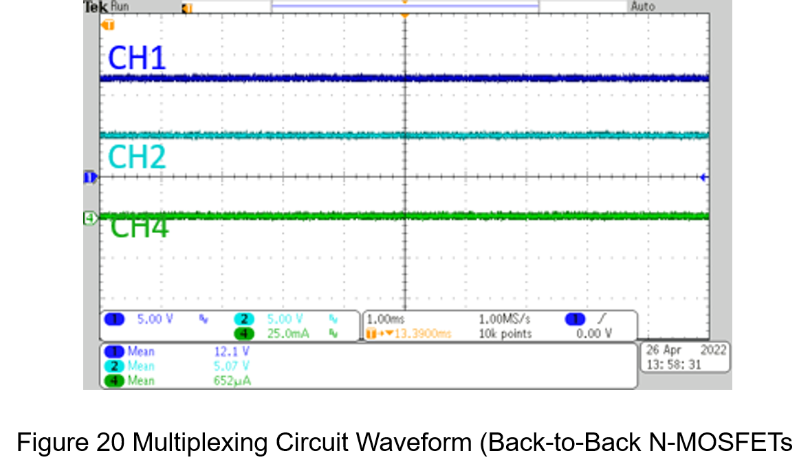
Figure 19 is the circuit that replaces a diode with a back-to-back N-MOSFETs, where the voltage and current measurement is shown in Figure 20. It can be seen that the reverse current is also effectively suppressed.
The data is summarized in
Table 2 .| Unprotected | diode | N-MOSFET | |
| Load voltage | 12.2V | 11.4V | 12.1V |
| Vin2 voltage | 11.1V | 5.07V | 5.07V |
| Vin2 current | -32.8mA | 782uA | 652uA |
The above two circuits compare the effect of unprotected、diode and back-to-back N-MOSFETs reverse current protection. The diodes provide the simplest way to protect, but the large forward voltage drop of the diode will increase losses and generate more heat; back-to-back N-MOSFETs due to Its low forward voltage and high current processing capability, compared to the diode, is more suitable for low power condition, and the disadvantage is the need of large area.
Conclusion
This article compares the application of two cases of MOSFET switching circuits. Without additional measures, the circuit is harmed by the reverse current; the two additional components play a significant role in protecting the reverse current, and the difference is that the diode has a large forward voltage drop, which is more unsuitable for use in battery systems. Back-to-back MOSFETs have a small forward pressure drop but need to overcome the problem of occupied area.
In view of the importance of reverse current protection, many power-electronic products on the market such as electronic fuses, load switches, etc., will integrate this function, so that users can meet the protection needs without additional components.
CTC is a professional service provider for high-end power supply modules (AC to DC Converter and DC to DC Converter) for critical applications worldwide since 30 years. Our core competence is to design and deliver products with leading technologies, competitive pricing, extremely flexible lead-time, global technical service and high-quality manufacturing (Made In Taiwan).
CTC is the only corporation certificated with ISO-9001, IATF-16949, ISO22613(IRIS), and ESD/ANSI-2020. We can 100% ensure not only the product, but also our workflow and service to match quality management system for every high-end application from the very beginning. From design to manufacturing and technical support, every single detail is operated under highest standard.