

You are here
Back to topHow to Extend the Service Life of Power Converters?
Power converters are critical components in electronic systems, and their service life directly affects the overall reliability and safety of the equipment. Extending the lifespan of a power converter not only improves product durability but also significantly reduces maintenance and replacement costs. This article examines the primary factors that influence power converter longevity, provides an overview of service life estimation and Mean Time Between Failures (MTBF) calculations, and presents five key design and application strategies for maximizing the service life of power converters.
Introduction
The reliability of a power converter can generally be considered from two perspectives: fault management and lifetime management.
Fault management focuses on catastrophic failures, such as implementing protection mechanisms and preventive measures against short-circuit or open-circuit events. In contrast, lifetime management emphasizes analyzing, estimating, and extending the operating life of the converter. This can be summarized into three core pillars: lifetime analysis, lifetime prediction, and lifetime extension.
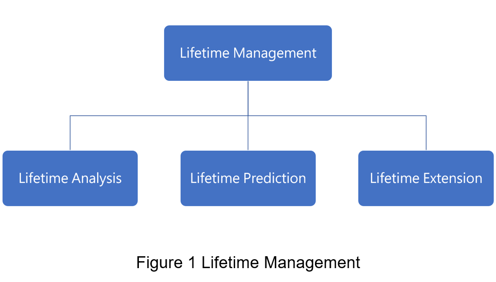
(1) Lifetime Analysis
The objective of lifetime analysis is to identify the critical components and dominant degradation mechanisms that govern the service life of a power converter. In switched-mode power supplies (SMPS), longevity is primarily determined by the degradation rates of power semiconductors and passive components subjected to long-term operational stress.
Power Switching Components
Power semiconductors experience switching losses and thermal stress during high-frequency operation. Selecting the appropriate device technology is therefore crucial for meeting specific application requirements:
-
Metal-Oxide-Semiconductor Field-Effect Transistors (MOSFETs):
MOSFETs feature low conduction losses and fast switching speeds. Due to their relatively limited voltage ratings, they are typically used in high-frequency, low-to-medium power applications. -
Insulated Gate Bipolar Transistors (IGBTs):
IGBTs are capable of handling high voltages and currents, albeit with slower switching speeds. They are well suited for high-power, lower-frequency applications such as uninterruptible power supplies (UPS). -
Silicon Carbide (SiC) Devices:
SiC devices offer high voltage blocking capability, low switching and conduction losses, and superior thermal performance. As a result, SiC technology is preferred for high-frequency, high-power, and high-temperature environments, including solar inverters and EV charging infrastructure. -
Gallium Nitride (GaN) Devices:
GaN devices are characterized by ultra-fast switching speeds and high power density. They are particularly effective for high-efficiency designs, RF applications, and advanced high-frequency power architectures.
Under continuous high-frequency switching conditions, thermal stress and electrical stress become the primary drivers of component aging, directly affecting the converter’s long-term energy conversion efficiency and reliability.
Capacitors
Capacitors play a critical role in ripple suppression and energy storage and are often the primary life-limiting components in power converters. Taking aluminum electrolytic capacitors as an example, the internal electrolyte gradually evaporates due to elevated ambient temperatures and self-heating caused by ripple current. This degradation process results in an increase in equivalent series resistance (ESR) and a reduction in capacitance.
Once these parameters exceed critical thresholds, output voltage instability and excessive noise may occur. Consequently, effective thermal management and appropriate capacitor selection are strongly correlated with overall system longevity.
(2) Lifetime Prediction
To assist users in evaluating the expected operational life of a product, power converters are subjected to rigorous reliability validation tests, such as the Operating Life Test (OLT). The failure-rate trend (λ) of an electronic product over time is typically described by the bathtub curve (as shown in Figure 2). The product lifecycle can be divided into three distinct stages:
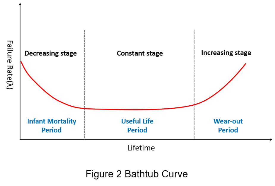
(A) Infant Mortality Period
Failures during this phase are primarily caused by design deficiencies, critical component defects, or process instability. To reduce early-life failures, manufacturers typically perform burn-in testing or Environmental Stress Screening (ESS) to improve product consistency and ensure delivered reliability.
(B) Useful Life Period
After passing the infant mortality phase, products enter a stable operating period in which the failure rate drops to a low level and remains approximately constant. Failures in this phase are generally random in nature and are often triggered by unexpected electrical stresses—such as inrush current or voltage transients—or by exposure to environmental conditions beyond component ratings.
(C) Wear-out Period
As operating time accumulates, internal components (such as aluminum electrolytic capacitors and cooling fans) and mechanical materials undergo irreversible degradation due to physical and chemical aging mechanisms, leading to a significant increase in the failure rate. Through accelerated life testing (ALT), key reliability parameters—including mean time to failure (MTTF) and failure rate—can be estimated.
Accelerated Life Testing and Evaluation
To validate long-term service life within a limited timeframe, accelerated stress testing is widely used across the industry. Common approaches include:
-
High-Temperature Operating Life (HTOL): Accelerates thermally driven aging mechanisms by operating the product at rated load under elevated-temperature conditions.
-
Low-Temperature Operating Life (LTOL): Evaluates whether parameter drift under extreme low-temperature conditions (e.g., increased capacitor ESR) affects overall system stability.
In addition to temperature stress, combined stress conditions—such as humidity (e.g., THB testing), input-voltage variation, and output-current loading—may be applied to build a comprehensive lifetime prediction model and to define effective application strategies for extending overall system operating life.
Mean Time Between Failures and Mean Time to Failure
MTTF and MTBF are standard reliability metrics used to characterize the time-related aspects of failure behavior. However, their applicable contexts differ depending on repairability:
-
MTTF (Mean Time to Failure): Used for non-repairable products, or products for which repair is not cost-effective.
-
MTBF (Mean Time Between Failures): Used for repairable systems or high-value equipment that can be restored to service after a failure.
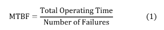
MTBF is a key benchmark for evaluating the reliability and stability of power converters. It represents the average elapsed time between inherent failures during the stable operating phase (the useful life period). A higher MTBF indicates a lower failure rate and greater robustness. The MTBF can be calculated as follows:
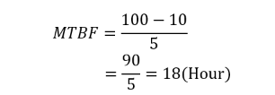
For example, if a power converter accumulates 100 hours of total operating time and experiences five failures during that period, the MTBF is calculated as follows:
MTBF can also be derived from the failure rate. The failure rate represents the frequency of failures occurring during the normal operating period of a power converter. Because the failure rate of power converters is typically very low, it is often expressed in Failures in Time (FITs), which denotes the number of failures per 109 hours of operation. The relationship between the failure rate and MTBF is expressed by the following equation:
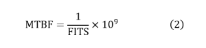
If the failure rate of a power converter is 1000 FITS, the MTBF can be calculated using the following formula:
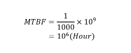
The converter fails once every million hours of operation.
Methods for Extending Service Life
To minimize maintenance costs and reduce replacement frequency, both component selection and circuit design should be carefully considered. The following strategies outline key approaches for maximizing the service life of power modules:
(1) Optimizing Component Selection
For power switching devices, the four semiconductor technologies discussed earlier each offer distinct advantages and trade-offs. In performance-overlap regions, device selection should be based on a balanced evaluation of switching frequency, thermal management constraints, and system efficiency targets. The table below summarizes the key characteristics of each switching device technology.
| operational characteristics | sequence (high to low) | |||
| Operating Frequency |
GaN (MHz↑) |
SiC (kHz) |
MOSFET (kHz) |
IGBT (30 kHz↓) |
| Withstand Voltage |
IGBT (<6.5kV) |
SiC (<3.3kV) |
GaN (900V↓) |
MOSFET (600V↓) |
| Thermal Conductivity |
SiC |
GaN | MOSFET | IGBT |
Capacitor Selection
Furthermore, capacitors are the passive components most susceptible to stress within a power module. The most commonly used solutions include aluminum electrolytic capacitors and multilayer ceramic capacitors (MLCCs):
-
Aluminum Electrolytic Capacitors:
These capacitors offer high capacitance and cost advantages but are limited by electrolyte dry-out over time. Design considerations should prioritize models rated for long life, high-temperature operation, and low equivalent series resistance (ESR). -
MLCCs:
MLCCs are ideal for high-frequency filtering applications due to their low ESR, compact footprint, and excellent aging characteristics. Although they exhibit lower capacitance density and higher cost compared to electrolytic capacitors, MLCCs are critical for improving longevity in high-reliability, compact power modules.
International Standards and Quality Assurance
Beyond physical characteristics, supplier compliance with international certification standards is a critical selection criterion. Priority should be given to components that have undergone third-party verification. Compliance with these standards ensures component robustness under extreme operating conditions and effectively mitigates failure risks during long-term operation.
(2) Establishing Efficient Thermal Management
Thermal stress is one of the primary drivers of system failure. Whether caused by high ambient temperatures or internal power losses within the converter, elevated temperatures significantly degrade system reliability—particularly the service life of aluminum electrolytic capacitors. Establishing an efficient thermal path is therefore essential for alleviating thermal stress. Common thermal management techniques include:
-
Thermal Interface Materials (TIMs):
The use of thermal grease or pads reduces contact thermal resistance between power components and heatsinks, thereby improving heat transfer efficiency. -
Heatsink Optimization:
Increasing heatsink surface area enhances heat exchange with the surrounding environment, accelerating heat conduction and dissipation. -
Active Cooling:
Forced convection using fans increases airflow and heat removal, making it suitable for high–power-density applications.
(3) Balancing Switching Frequency and Power Loss
The switching frequency of a power converter directly influences both efficiency and component lifespan. Power devices incur switching losses during each cycle; as the switching frequency increases, cumulative power loss per unit time rises accordingly.
While higher switching frequencies allow for reduced inductor and capacitor sizes—enabling system miniaturization—the resulting increase in thermal stress accelerates component degradation and complicates electromagnetic interference (EMI) suppression. Therefore, converter design must involve a careful trade-off among conversion efficiency, power density, EMI performance, and thermal balance to determine an optimal switching frequency that aligns performance objectives with long-term reliability.
(4) Comprehensive Protection Circuit Design
Under abnormal operating conditions—such as transient overvoltage events or sudden current surges—stress levels that exceed component ratings may lead to semiconductor breakdown or permanent hardware damage. To enhance system robustness, multiple protection mechanisms should be incorporated to mitigate diverse failure scenarios. Common protection features include:
-
Overvoltage Protection (OVP)
-
Overcurrent Protection (OCP)
-
Short-Circuit Protection (SCP)
-
Over-Temperature Protection (OTP)
-
Under-Voltage Lockout (UVLO)
These protection mechanisms enable the converter to automatically enter a safe operating state or shut down under extreme stress conditions, thereby preventing catastrophic system failure.
(5) Adherence to Application Notes and Derating Design
Users must strictly adhere to the parameter limits and operational guidelines specified in the product datasheet to ensure operation within the Safe Operating Area (SOA). Key application considerations include:
-
Input Voltage Compliance:
Ensure operation remains within the specified input voltage range to prevent startup instability or overcurrent conditions triggered by UVLO. -
Thermal and Environmental Management:
Adjust operating load in accordance with derating curves to prevent elevated ambient temperatures from accelerating component aging. -
Rated Load Management:
Avoid prolonged operation beyond the rated load to minimize thermal fatigue and electrical stress on internal power components.
Conclusion
The service life of a power converter has a direct impact on system reliability and long-term operational costs. Key factors influencing longevity include the selection and characteristics of critical components—such as power switches and capacitors—operating temperatures (including hotspot temperatures), and the loss and stress levels associated with switching frequency.
Through service life estimation and failure-rate analysis using metrics such as MTTF and MTBF, reliability performance can be quantitatively assessed to guide design decisions. In practice, the integration of high-reliability components, effective thermal management, optimized switching frequency selection, and comprehensive protection mechanisms—combined with strict adherence to datasheet specifications and proper maintenance—can significantly reduce stress and degradation rates. These measures effectively extend the service life of power converters while lowering maintenance and replacement costs.
CTC is service provider for high-end power modules (DC to DC Converter and AC to DC Converter) for critical applications worldwide since 1987. We aim to be business generator and a virtual business unit. CTC is your own team with 35 years of experience for a strong business program from market research, product definition & development, supply chain management and total technical services.
CTC is the only corporation certificated with ISO-9001, IATF-16949, ISO22613(IRIS), and ESD/ANSI-2020. We can 100% ensure not only the product, but also our workflow and service to match quality management system for every high-end application from the very beginning. From design to manufacturing and technical support, every single detail is operated under highest standard.