

You are here
Back to topUsing Remote Sense to Reduce IR Drop
When a power converter supplies power to a load, the actual voltage at the load may be lower than the converter’s rated output voltage. This condition is typically caused by two main factors: excessive ripple in the output voltage and voltage drop (IR drop) resulting from the impedance of the transmission path.
This article introduces the remote sensing (Remote Sense) function of DC converters. This feature directly connects the sensing pins to the load and compensates for the IR drop in the transmission path, thereby improving the accuracy of the load voltage. Finally, the effectiveness of the remote sensing function is verified through experiments to evaluate its ability to reduce IR drop in the circuit.
Introduction
IR drop refers to the voltage drop that occurs when current flows through a resistance. It not only reduces conversion efficiency but can also affect normal system operation. According to Ohm’s law, when the current is fixed, the line resistance is directly proportional to the resulting IR drop. Therefore, reducing line resistance helps minimize power loss and improve conversion efficiency.
In addition to reduced efficiency, excessive IR drop may lead to the following issues:
- Degradation of electrical performance: As IR drop increases and the voltage at the load falls below the device’s rated input voltage, device performance may be degraded. For example, fan speed may decrease, and the heating performance of a water heater may be reduced.
- System startup failure: If the voltage at the load is lower than the device’s startup voltage, an undervoltage protection mechanism may be triggered, preventing the device from operating. If the system does not include undervoltage lockout (UVLO), the device may enter a partial conduction state, further increasing standby power consumption.
- Increased heat loss: For devices that require stable power, such as air conditioners and refrigerators, a drop in input voltage causes the device to draw higher current to maintain the required power. This increased current can lead to heating of the wiring and internal components and, in severe cases, may damage the equipment or trigger over-temperature protection.
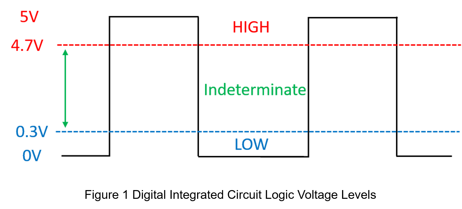
- Digital logic errors: In digital circuits, ICs require a stable supply voltage to ensure correct logic operation. If the IR drop is excessive, it may cause errors in distinguishing high and low voltage levels at the IC pins, thereby affecting overall system operation. Figure 1 illustrates logic-level determination in digital circuits, where both high and low logic levels have a 0.3 V tolerance margin. Once the input voltage error exceeds 0.3 V, the IC pin can no longer correctly identify the current logic state.
In summary, IR drop is a critical factor in the stable operation of electronic devices. Reducing IR drop helps ensure that the system input voltage remains close to its rated value, thereby maintaining proper device functionality. This article explores various methods for reducing IR drop, with a particular focus on how the remote sensing function of DC converters compensates for IR drop in transmission paths. Finally, experiments are conducted to verify the effectiveness of remote sensing in improving the load voltage.
Methods to Reduce IR Drop
To effectively mitigate the impact of IR drop on load voltage, this article proposes three strategies for reducing line resistance:
(1) Shorten the distance between the power converter and the load
The resistance of a copper conductor is directly proportional to its length and inversely proportional to its cross-sectional area. Therefore, if a system is highly sensitive to IR drop, the wiring distance between the converter and the load should be minimized within the available space to reduce conductor resistance. In addition, increasing the width of the copper trace increases its cross-sectional area, further reducing resistance and improving current-carrying capability.
(2)Increase the PCB copper foil thickness
In addition to increasing the width of PCB copper traces, the thickness of the copper foil also affects electrical resistance. Copper foil thickness is typically specified in ounces (oz), which represent the thickness achieved when 1 oz of copper is uniformly distributed over an area of one square foot. For example, a 1 oz copper foil has a thickness of approximately 35 µm.
Common PCB copper foil thicknesses include 1 oz, 2 oz, and 3 oz, with 2 oz or 3 oz commonly selected for power converter applications. Increasing copper thickness not only enhances current-carrying capability and reduces resistance but also improves heat dissipation.
(3)Remote sensing
DC converters are typically equipped with a remote sensing (Remote Sense) function. By connecting the Remote Sense pins directly to the load side, the converter can accurately measure the load voltage. This sensed voltage is then fed back to the converter, where the internal control circuitry adjusts the output voltage to maintain the rated voltage at the load terminals, as illustrated in Figure 2.

Converters with remote sensing feature two sense pins: +Sense and −Sense. When this function is used, the +Sense pin should be connected to the positive output terminal and routed to the positive terminal of the load, while the −Sense pin should be connected to the negative output terminal and routed to the negative terminal of the load. The closer the +Sense and −Sense connections are to the load, the smaller the effective series resistance sensed by the converter.
It is important to note that if remote sensing is not used, the +Sense and −Sense pins must not be left floating. Instead, the +Sense pin should be connected directly to the positive output terminal using the shortest possible path, and the −Sense pin should be connected directly to the negative output terminal. In typical PCB layouts, the +Sense pin is shorted to the positive output solder pad, and the −Sense pin is shorted to the negative output solder pad, as illustrated in Figure 3.

To implement remote sensing and reduce wiring impedance, the basic principle is to lower the equivalent resistance by connecting conductors in parallel. Figures 4 and 5 illustrate the equivalent circuit diagrams without and with remote sensing connections, respectively.


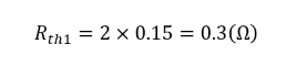
For Figure 4, the equvialent resistance Rth1 seen from terminals A and B is 2Rwire.
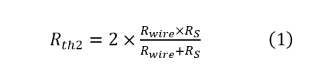
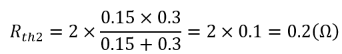
For Figure 5, the equivalent resistance Rth2 seen from terminals A and B is :
If Rwire = 0.15Ω, Rs= 0.3 Ω, then:
Given that Vo=12V and the load current Io=10A, we can calculate the load voltages VAB1 and VAB2 for figures 4 and 5 respectively:
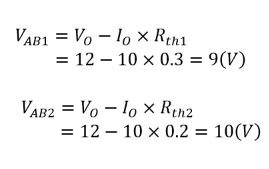
The calculation results clearly demonstrate that the equivalent resistance is reduced after implementing remote sensing, thereby achieving the objective of minimizing IR drop.
In addition to reducing IR drop through wiring configuration, remote sensing can also compensate by adjusting the converter’s output voltage. However, for loads with high output current, simply increasing the converter’s output voltage does not reduce the IR drop across the wiring and may, in fact, increase the risk of converter overheating.
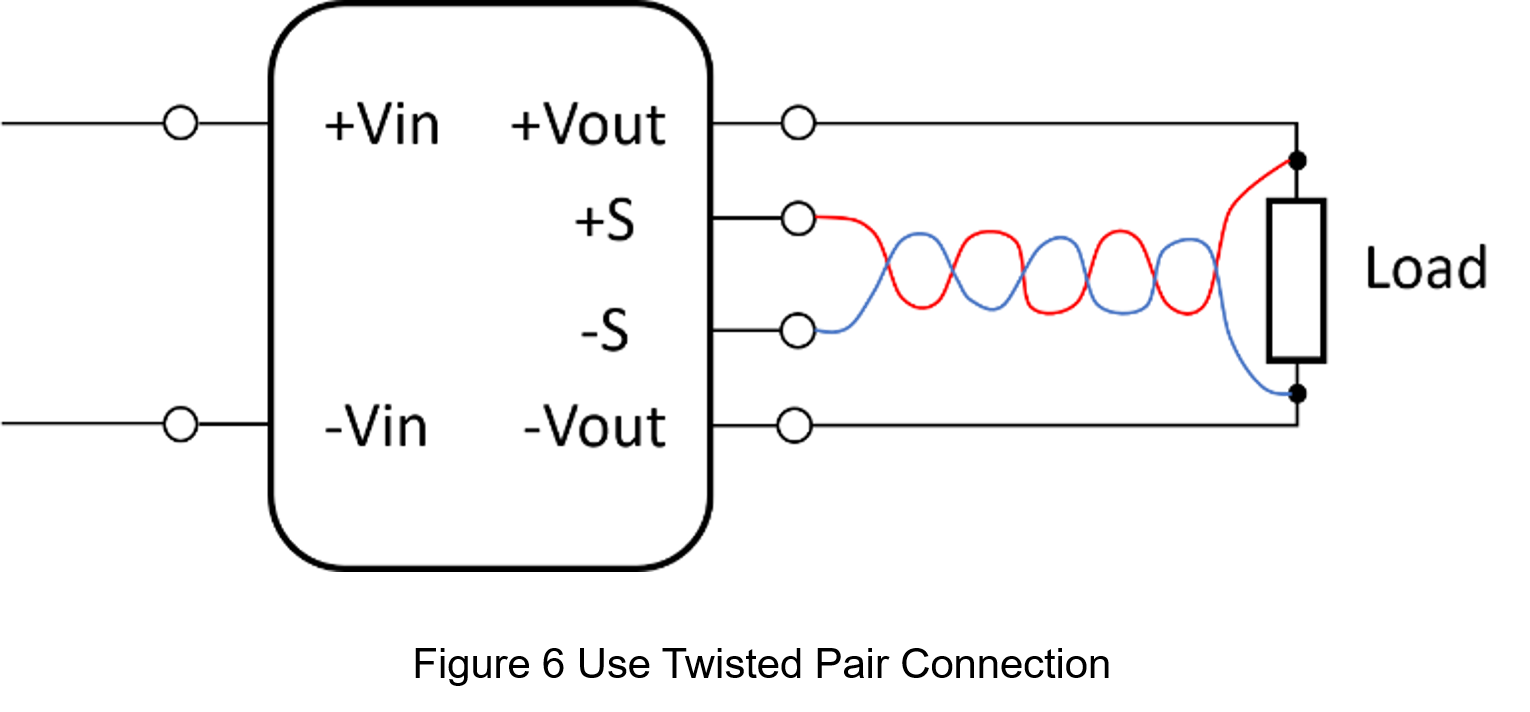
When implementing remote sensing, it is recommended to use shielded twisted-pair (STP) cables for the sense lines. This helps reduce signal attenuation during transmission and minimizes susceptibility to noise interference. Using twisted-pair cables with differently colored conductors also improves visibility and helps prevent incorrect connections, which could otherwise pose potential safety risks.
Experiment
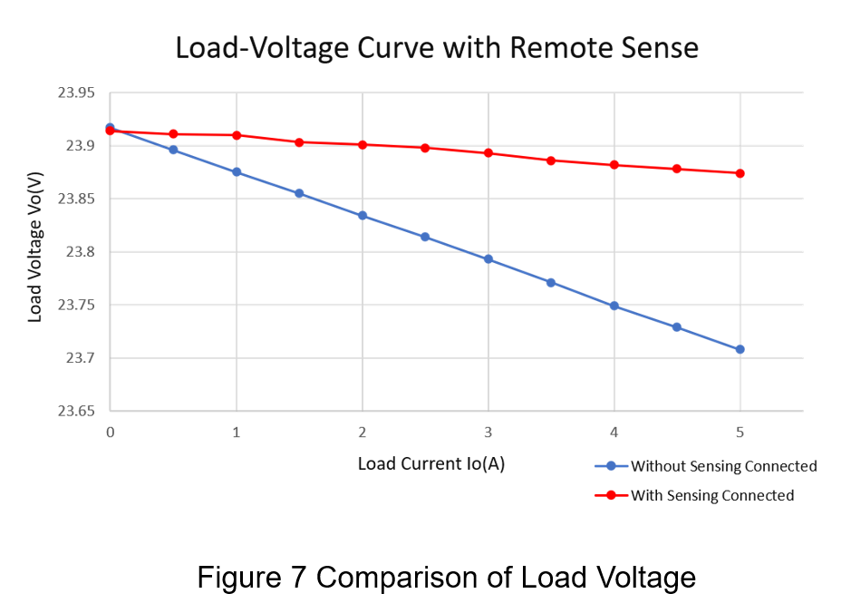
The experiment uses an isolated DC-DC converter connected to a power supply and an electronic load. The power supply provides an input voltage of 48 V, while the load current is adjusted by configuring the electronic load. The test is conducted from no load (0 A) to full load (5 A), with the output voltage recorded at 0.5 A intervals using a digital multimeter. The experiment is performed twice: once without the sensing pins connected and once with the sensing pins connected.
Figure 7 presents the experimental results. By comparing the two curves, it is evident that when the sensing pins are connected, the load voltage variation is more stable as the load current increases, and the output voltage remains closer to the target value of 24 V.
The load regulation with the sensing pins connected is 0.168%, whereas the load regulation without sensing is 0.882%, indicating a significant improvement. Detailed experimental data are provided in Table 1.
| with the sensing pins connected | without the sensing pins connected | ||
| No load voltage(V) | 23.914 | No load voltage(V) | 23.917 |
| Full load voltage(V) | 23.874 | Full load voltage(V) | 23.708 |
In addition to load regulation, the impedance from the converter output to the load can also be calculated based on the experimental data. The measured line impedance with the sensing pins connected is 8 mΩ, whereas the impedance without the sensing pins connected is 41.8 mΩ. The resulting impedance difference is approximately a factor of five, clearly demonstrating that the sensing pins are highly effective in reducing line impedance.
The experimental results confirm that the converter’s remote sensing function, as predicted by theoretical analysis, helps reduce IR drop along the transmission path, allowing the load voltage to remain close to its rated value even under heavy load conditions.
Conclusion
This paper demonstrates that the remote sensing function of a converter can effectively reduce line IR drop. It first explains the impact of IR drop on system performance and introduces three effective methods for mitigating IR drop, with remote sensing as the primary focus. The analysis begins with a theoretical impedance derivation, followed by an experimental comparison between cases with and without remote sensing. The results confirm that the converter’s remote sensing function significantly reduces line voltage drop and helps maintain stable system operation.
CTC is service provider for high-end power modules (DC to DC Converter and AC to DC Converter) for critical applications worldwide since 1987. We aim to be business generator and a virtual business unit. CTC is your own team with 35 years of experience for a strong business program from market research, product definition & development, supply chain management and total technical services.
CTC is the only corporation certificated with ISO-9001, IATF-16949, ISO22613(IRIS), and ESD/ANSI-2020. We can 100% ensure not only the product, but also our workflow and service to match quality management system for every high-end application from the very beginning. From design to manufacturing and technical support, every single detail is operated under highest standard.