

You are here
Back to topThe Common Mode Choke: From Working Principle to Selection Criteria
ISO establishes standards for electromagnetic compatibility (EMC) in electrical and electronic systems to prevent electromagnetic interference that could distort signals. Before bringing a power converter to market, designers must ensure that electromagnetic radiation is kept within the limits defined by relevant regulations. A common design approach to achieving this is the use of common-mode chokes, which effectively filter common-mode noise in switching power supplies. This article first introduces the operating principle of common-mode chokes with respect to common-mode and differential-mode signals, with the corresponding signal paths clearly identified.
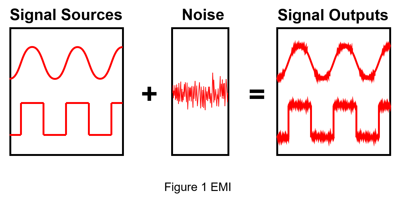
After an electronic product is powered on, electromagnetic waves are generated due to electromagnetic induction, which can cause electromagnetic interference (EMI) to nearby electronic devices. This effect is especially pronounced in high-power power supplies during rapid energy switching, as shown in Figure 1. EMI may be transmitted through conductors or radiated through the air, potentially affecting sensitive circuits.
For example, when multiple electronic devices in a household share the same electrical circuit, switching on one device may cause another to malfunction. Likewise, when a vehicle passes by a commercial building or telecommunications facility, radio signals emitted from exterior antennas may interfere with the operation of receivers inside the car.
Therefore, achieving better electrical performance and system reliability makes EMI suppression in switching power converters a key challenge for every designer. Today, many solutions exist to address this issue, such as reducing parasitic effects in PCB traces, adding buffering circuits, and minimizing the length of high-current loops. However, even with an optimized PCB layout, many systems still require additional filtering. Among these solutions, a critical component in the input filter is the common-mode choke.
A common-mode choke is a filter that blocks high-frequency noise common to two or more signal or power lines, while allowing desired-frequency signals to pass through. Common-mode chokes are widely used in switching power supply circuits for noise filtering. Despite their widespread adoption, many users remain unfamiliar with their function and basic operation. The following sections provide a detailed explanation of the types and operating principles of common-mode chokes.
Signal Path of Common Mode Choke
A common-mode choke, also known as a common-mode inductor, consists of two or more insulated coils wound on a single ferrite core. The typical construction involves winding two copper wires with the same number of turns symmetrically around a toroidal ferrite core. The device operates in two modes: one in which current flows in the same direction through the windings, and another in which current flows in opposite directions. These are referred to as the common mode and differential mode, respectively.
As a result, the magnetic field distribution of the common-mode choke differs under differential-mode and common-mode conditions, leading to different impedance effects on noise. This means that the noise attenuation characteristics vary significantly between the two modes. The simplified circuit diagram below illustrates this behavior, where the common-mode choke is placed in series with the power converter.
(1) Differential Mode
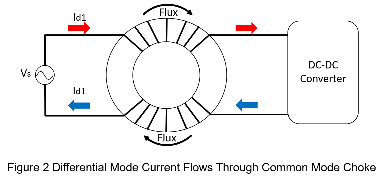
When differential-mode current flows through the two coils, the magnetic field directions within the toroidal ferrite core oppose each other. According to Faraday’s law and the right-hand rule, when current enters the common-mode choke, the return current from the input source also flows through the choke. At this point, the magnetic flux generated in each winding is equal in magnitude but opposite in direction, causing the flux to cancel out. As a result, the differential-mode inductance is nearly zero, allowing the differential-mode signal to pass through with minimal attenuation.
To calculate the differential-mode impedance, the input voltage is divided by the differential-mode input current:
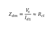
Where Rcl represents the copper loss due to winding resistance.
Ideally, the magnetic flux density of a common-mode choke does not increase under differential-mode current. This means that even when a large differential-mode current flows through the choke, it will not drive the core into magnetic saturation.
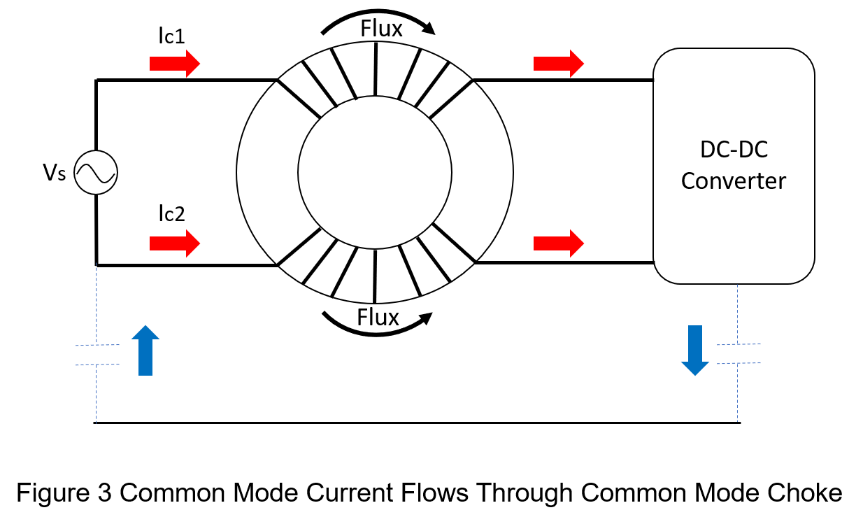
(2) Common Mode
When common-mode current flows through the two coils, the magnetic field directions within the toroidal ferrite core are the same. According to Faraday’s law and the right-hand rule, when common-mode current enters the coils of the common-mode choke, the magnetic flux generated in each winding is equal in magnitude and aligned in the same direction. Instead of canceling, the two fluxes add together, resulting in a relatively large inductance. This high inductance produces a high impedance to common-mode noise, preventing common-mode current from entering the power converter.
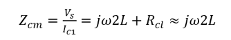
To calculate the common-mode impedance, the input voltage is divided by the input common-mode current:
It is recommended that users design the coils according to the rated current specified by the manufacturer, as exceeding this rating may increase magnetization and lead to magnetic saturation.
How to Choose a Common Mode Choke?
When selecting a common mode choke based on the user's application, some key items to check in the datasheet include:
- Winding Resistance
This refers to the winding resistance within the common-mode choke, which improves the damping characteristics of the filter, especially at high frequencies. Since the inductance of the common-mode choke can resonate with the system’s input capacitance or with parasitic capacitances in the PCB traces, the damping effect provided by the winding resistance is beneficial. However, the drawback is that excessively high winding resistance increases the voltage drop between the input and output and also results in higher heat generation.
- Common Mode Attenuation Range
The attenuation of common-mode signals by a common-mode choke varies with the noise frequency. If the noise frequency range is known, the user can determine the required bandwidth of the common-mode choke.
- Rated Current
The rated current of a common-mode choke is defined based on the allowable temperature rise of the device. However, the actual temperature rise depends on factors such as placement, the cross-sectional area of the winding, and the availability of ventilation. These factors limit the types of systems in which a choke can be used, as well as its allowable placement within the system.
- Common Mode Impedance and Differential Mode Impedance
When selecting a common-mode choke, the user should consider both its common-mode and differential-mode impedances. The frequency range of the common-mode interference must first be determined. Within this range, a higher common-mode impedance provides greater attenuation of common-mode noise. Conversely, the differential-mode impedance should be as low as possible so that the differential signal can pass through the filter without degradation.
Therefore, the ideal choice is a common-mode choke that exhibits the highest common-mode impedance and the lowest differential-mode impedance within the required frequency range. To illustrate the relationship between impedance and frequency, the following diagram shows the common-mode and differential-mode impedance characteristics of a common-mode choke.
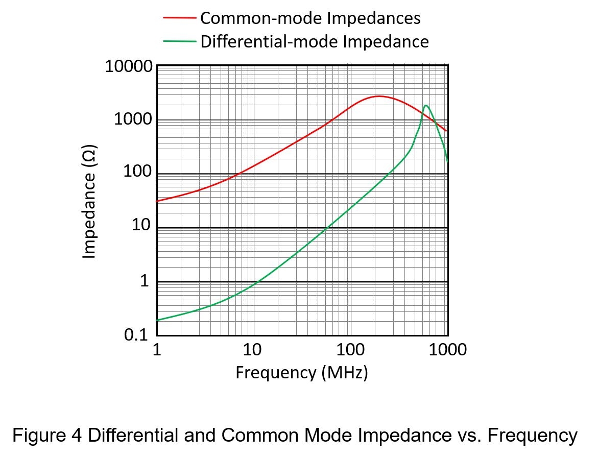
From Figure 4, it is clear that when the frequency is below 200 MHz, the common-mode impedance is significantly higher than the differential-mode impedance, indicating that the common-mode choke is suitable for operation within this frequency range. However, once the frequency exceeds 200 MHz, the differential-mode impedance increases rapidly, and the gap between the two impedances gradually narrows. At this point, the filter can no longer effectively attenuate only the common-mode interference.
Conclusion
Today, all electronic products prioritize signal integrity, ensuring that signals entering the system are properly filtered to remove potential noise. Therefore, using a common-mode choke can reduce common-mode interference while allowing differential-mode signals to pass with minimal attenuation. In addition, key selection criteria for a common-mode choke include low winding resistance, a wide common-mode attenuation range, a high rated current, and a significant difference between common-mode and differential-mode impedances within the applicable frequency band.
CTC is service provider for high-end power modules (DC to DC Converter and AC to DC Converter) for critical applications worldwide since 1987. We aim to be business generator and a virtual business unit. CTC is your own team with 35 years of experience for a strong business program from market research, product definition & development, supply chain management and total technical services.
CTC is the only corporation certificated with ISO-9001, IATF-16949, ISO22613(IRIS), and ESD/ANSI-2020. We can 100% ensure not only the product, but also our workflow and service to match quality management system for every high-end application from the very beginning. From design to manufacturing and technical support, every single detail is operated under highest standard.