

You are here
Back to topEMI Radiated Emission Limitations in Various Application
Many countries provide radiated emission protection regulations, limits, and safety levels for users of electronic equipment. Power converter suppliers have also proposed product design countermeasures to reduce radiated emission values. The following will introduce the test environment and standards for radiation emission, particularly to multimedia, industrial, automotive, and lighting equipment.
Introduction
Electromagnetic Interference (EMI) is caused by electromagnetic waves generated when electronic products are in operation. It may be affected by various sources and paths. For example, when cars pass by commercial buildings or telecommunication companies, the broadcast antennas of radio signals outside the vehicle may interfere with the receiver's function in the car. EMI sources are classified as follows:
- Man-Made: This typically originates from other electronic circuits, such as radio devices like wireless mobile phones, which continuously emit electromagnetic waves and radar signals. The high rate of current change (di/dt) produced in power converters is likely to cause fluctuations in the magnetic field, leading to both low-frequency and high-frequency noise being coupled to the voltage source.
- Natural-made: This occurs typically due to natural events, such as electromagnetic radiation generated by lightning strikes or atmospheric disturbances, which can affect military aircraft or missile launches.
Different types of radiated disturbances can also be classified according to broadband,
- Narrowband: This form is just a single wave source, which may be generated by a radio transmitter.
- Broadband: This form is a variety of wave sources. The man-made broadband source may be an arc welder that continuously generates sparks or equipment failures that cause many frequency radio signals.
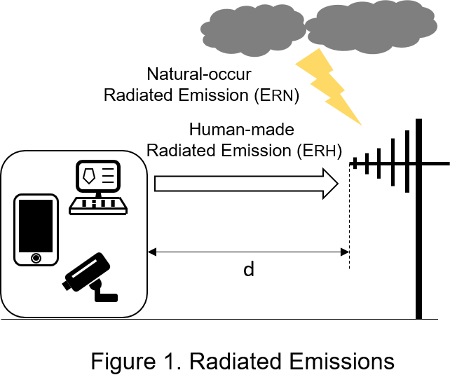
Figure 1 shows the source of radiation emission, the distance between antenna and electronic equipment is d, the man-made radiation energy ERH of electronic equipment and the natural-made radiation energy ERN of lightning, which will spread to the surroundings, and the intensity of radiation interference received by the antenna will be proportional to In ERH and ERN, inversely proportional to d.
For industrial, medical or railway application regulations, the company uses professional equipment to test whether the EMI of each power converter passes the standards. Users can choose right power converters that have passed international standard certification, so ensure to reduce the impact of electromagnetic interference. This article focuses on the experimental environment and precautions for radiated emissions and EMI standards for radiated emissions for especially those related to automotive, information, and industrial applications.
Radiated Emission Test
Radiated emission refers to the degree of electromagnetic interference generated by the device, and the electromagnetic energy is returned to the power source through magnetic coupling or capacitive coupling, and its frequency ranges from 30 MHz to 1GHz. Since power supply circuits are connected to many sensitive circuits, it is very important to correctly measure EMI-radiation.
Radiated emission test is implemented in an environment without electrical interference, such as a semi-anechoic chamber (SAC) or an open area test site (OATS). The semi-anechoic chamber consists of absorber materials, a nonconductive turntable for DUT(device under test), a power supply, a preamplifier, a spectrum analyzer, an EMI receiver, and a broadband antenna. The measurement environment diagram is as depicted in figure 2. The DUT is placed on an insulating turntable 0.8m above the reference ground plane, such as a dry wooden table, and placed 3m or 10m away from the bandwidth antenna, which is installed on the antenna tower, and the height Adjusted between 1m and 4m above the ground plane, finally amplify the radiated signal through the preamplifier and then send it to the EMI receiver. The calibrated bandwidth antenna can detect radiated signals both horizontally polarized (passing parallel to the ground plane) and vertically polarized (rotated 90 degrees relative to the ground plane), and frequency range spanning 30MHz to 1GHz. During measurement, the maximum electromagnetic radiation can be found from various directions through the DUT rotating 360 degrees on the turntable. Hence, the maximum radiation emission can be received by changing the angle between bandwidth antenna and DUT.
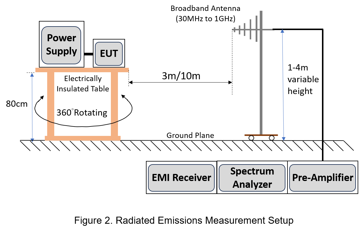
The walls and ceiling in SAC are covered with absorbing materials, and the plastic floor is be used. When radiated emission testing, the electromagnetic energy emitted by the DUT will be reflected from the ground to the antenna, which is closer to the actual situation.
Application Standards
Many international standards have specifying radiated emissions limits to prevent excessive electromagnetic interference. Those standards mainly vary according to the operating environment of product, such as different standards in medical, automotive applications, and residential and industrial environments. The following will let users to know radiated emission standards for various applications,
- EMI Standard for Automotive
Automotive systems use numerous microprocessors, radio frequency transmitters and receivers, and electric drive systems. When electronic devices are operating at the same time, EMI radiation will inevitably interfere with each other and then cause unstable control signals. Therefore, the assessment of radiated emissions from automotive electric motors needs be high concern.
- UNECE Regulation 10
United Nations Economic Commission for Europe (UNECE) Regulation 10 Revision 5 (referred to as R10.05) divides the radiated emission test of vehicles into two parts: broadband (BB) and narrowband (NB).
Broadband emissions, as the name implies, are interferences that occur over a wide frequency range. Broadband transmissions in vehicles are produced by different switching systems, such as electric motor systems including cooling fans and air conditioning; high power switching systems including on-board battery charging devices; Narrowband emission, as the name implies, is interference within a specific narrow frequency range, and typical sources are microprocessor clocks and switching DC-DC converters.
Assuming a Resolution Bandwidth (RBW) of 120kHz, the BB and NB radiated emission limits are measured using quasi-peak (QPK) and average (AVG), spanning applicable frequency range from 30MHz to 1GHz.
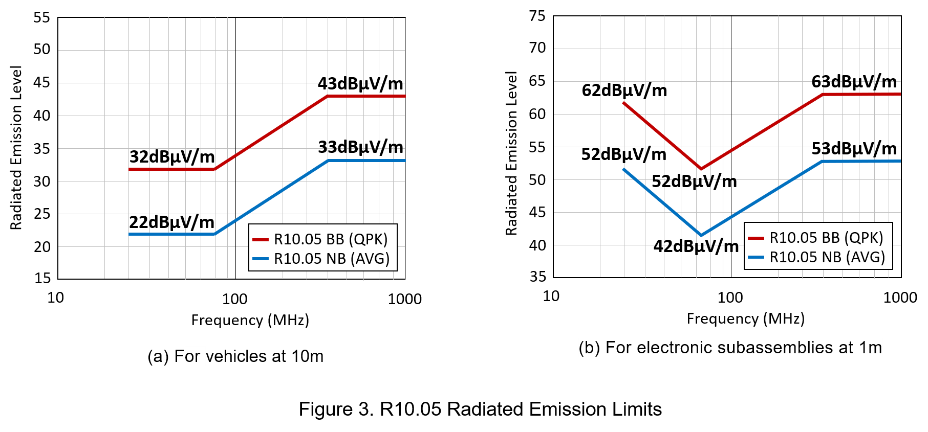
In Figure 3(a), the measuring antenna distance is 10m for vehicles, if the antenna is located at 3m for vehicle testing, an additional 10dB is required.
2. CISPR 12 and CISPR 25
International Special Committee on Radio Interference (CISPR) defines the radiated emissions limits and procedures, which protect vehicle's receivers inside and outside, respectively. When evaluating the test method of every product, it is very important to understand which standard to use. Taking CISPR 12 and CISPR 25 as examples, CISPR 12 is to protect the receiver outside the car to ensure that when the car passes by receivers installed outside of the house, the radiated emission car produced don't affect the receivers; CISPR 25 is to protect the receiver inside the car. It means to test the radiated emission of receivers (such as AM/FM radio or GPS) in the car produced.
- EMI Standard for IT and Multimedia
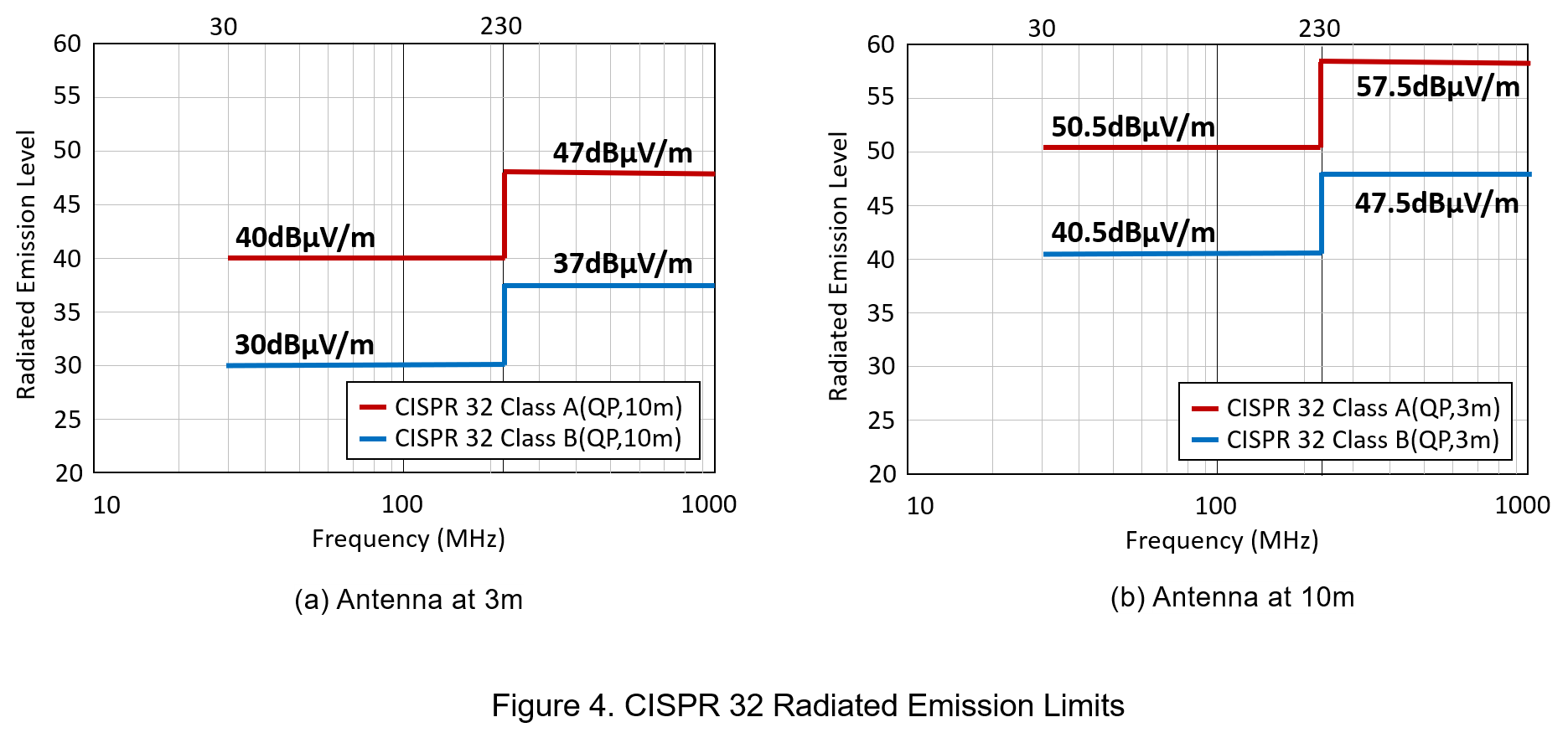
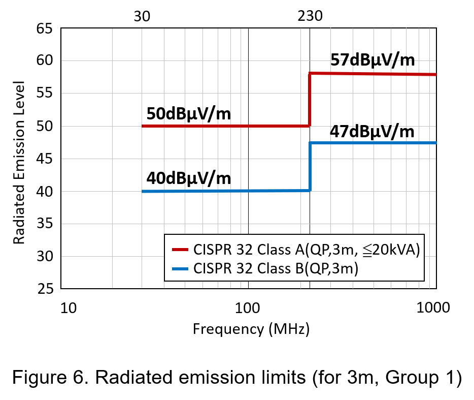
CISPR32 is specified that the radiated emission is only applicable to IT and multimedia equipment with a rated AC or DC power supply voltage not exceeding 600V, and the equipment is including audio, broadcast receivers, entertainment lighting controllers, etc., but not for radio transmitters. At present, CISPR 22/EN 55022 was recently subsumed into CISPR 32/EN 55032, which is as a new product family standard for electromagnetic interference of IT and multimedia, and then products sold in the EU must meet the requirements of CISPR 32/EN 55032. It divides the standard into two categories according to the type of environment where the product is used. Equipment mainly used in a residential environment must comply with Class B limits; all other equipment needs to follow Class A limits.
- EMI Standard for Industrial
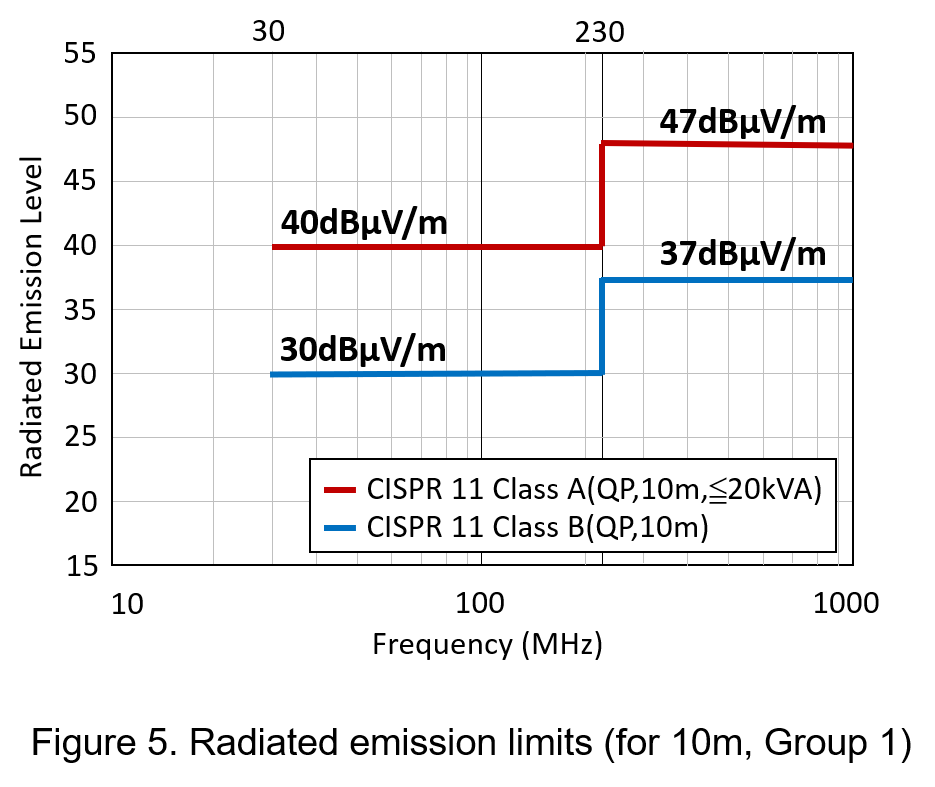
CISPR 11 is the international standard for conducted emissions from industrial, scientific and medical (ISM), which related to radio-frequency (RF) disturbances in the frequency range from 9kHz to 400GHz. CISPR 11 is suitable for a wide variety of equipment, including wireless power transfer (WPT) charging equipment, Wi-Fi systems, microwave ovens, X-ray machines and electronic arc welders. CISPR 11 divides ISM equipment into two categories. Group 1 ISM equipment in which there is intentionally self-generated and/or inductive or capacitive coupled RF energy, which is necessary for the ISM equipment itself; Group 2 ISM equipment is intentionally self-generated, and used in processing signal or analyzing data.
Each group is further subdivided ISM equipment in two classes:
- Class A: Equipment is permitted to be installed in all establishments other than domestic and can be measured at the test site or the installation site according to the manufacturer's regulations.
Class B: Equipment suitable for domestic use, also requiring measurements to be made at the test site.
A summary of the aforementioned international norms is shown in the table below.
| Market |
Equipment Type |
Standard | |
| IEC/ CISPR | EN | ||
| ISM | Industry, Science, Medical | CISPR11 | EN55011 |
| Vehicles, boats & devices with internal combustion engines | On-board Receivers | CISPR25 | EN55025 |
| Off-board Receivers | CISPR12 | EN55012 | |
| Multimedia | CISPR32 | EN55032 | |
| Household | Electrical Equipment | CISPR14-1 | EN55014-1 |
| Lighting | Lamps | CISPR15 | EN55015 |
Conclusion
Every electronic equipment may generate electromagnetic radiation disturbance during normal operation. During the stage of designing product, using professional instruments to measure power converter in semi-anechoic chamber can find the EMI radiation emission generated by the outer casing of the power converter in advance whether compliance with various standards for automotive, information technology, multimedia and industrial applications.
CTC is service provider for high-end power modules (DC to DC Converter and AC to DC Converter) for critical applications worldwide since 1987. We aim to be business generator and a virtual business unit. CTC is your own team with 35 years of experience for a strong business program from market research, product definition & development, supply chain management and total technical services.
CTC is the only corporation certificated with ISO-9001, IATF-16949, ISO22613(IRIS, AFNOR silver certificate), and ESD/ANSI-2020. We can 100% ensure not only the product, but also our workflow and service to match quality management system for every high-end application from the very beginning. From design to manufacturing and technical support, every single detail is operated under highest standard.