

You are here
Back to topThe Way of Over-Temperature Protection
Recently, many overheating electronic devices have damaged power transistors, shortened the life of transformers, and even caused system mis-operation. Therefore, when the temperature is too high, protection circuit of the power converter has become a necessary design. Next, it introduces the design of over-temperature protection circuit, and implements the power converter combined with the temperature-switch to determine the temperature protection point by adjusting external resistor, so as to avoid the risk of exceeding safe temperature.
Introduction
For common Computer Numerical Control (referred to CNC) in factories, electric ovens in homes or other high-power electronic equipment, the power converter is under heavy load for a long time or placed in high ambient temperature, when the case temperature is higher than the maximum temperature indicated in the specification, it possibly damages the internal devices of the power converter. In order to protect the power converter and the back-end circuits, temperature protection is necessary in the design. Over Temperature Protection (OTP) is used to prevent the power converter to avoid operating continuously over temperature condition and then cause component damage.
Generally, converter can be measured the case of center temperature as the standard for over-temperature protection, as shown in Figure 1. Once the case temperature exceeds the maximum temperature in the specification, the power converter will be stopped working. Therefore, it can provide proper cooling method to keep the case temperature below the maximum case temperature to reduce overheating.

The high-reliability power converter is designed with built-in over-temperature protection, which can quickly detect temperature changes and trigger the protection mechanism immediately. On the other hand, if the user gets power converter without built-in over-temperature protection mechanism, how to realize the over-temperature protection function? It can be achieved by adding temperature switch.
This article explains the over-temperature protection function, and implements power converter with a programmable temperature switch, TMP708, soldered adjacent in the printed circuit board, to achieve over-temperature protection as the focus of this experiment.
Over Temperature Protection
DC/DC power converters continuously operate in overvoltage or overcurrent conditions for a long time, which causes especially the internal temperature to be high, and then the start-timing of over-temperature protection is determined by detecting the central case temperature. Over-temperature protection immediately shuts down the converter output voltage until temperature drops below the recovery value, the converter automatically restarts and then the output voltage returns to the standard value.
Figure 2 shows the basic architecture of flyback converter with internal temperature sensor. The sensor measures the heat-energy released by the power converter, and it varies with depending on the distance the placed sensor. The temperature sensor is adjacent to the high-temperature device so that be more sensitive to temperature; otherwise, if the temperature sensor is far away from the high-temperature device, the maximum temperature value cannot be obtained immediately. So , when the center temperature of case has reached the maximum level, the temperature sensed by sensor has not yet reached the critical point, maybe resulting to cause danger.
When operating in heavy load, heat-energy is transferred to the temperature sensor through the printed circuit board. Once the temperature is higher than the critical temperature, the primary side circuit is disconnected,
stopping energy conversion, and finially the power converter will be turned off.
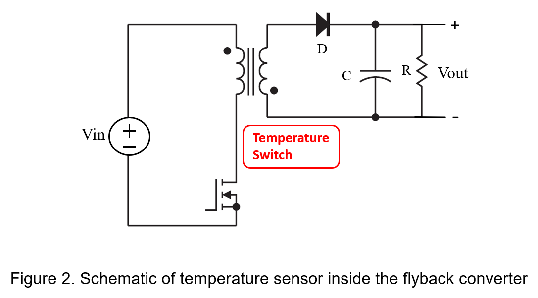
Figure 3 shows the basic architecture of a flyback converter with an external temperature switch. First, select a power converter that provides positive logic and remote control switch function, and the control pin (Ctrl) can make the converter enter standby mode, or enable to restart. Next, putting the temperature switch to close to the shell of the heat-generating device (i.e. M1) of the power converter to ensure that temperature can be transmitted to thermo-sensor. When the temperature is too high, temperature switch is turned on so that the control signal is pulled to ground and turns converter off.

Although it is not as accurate as the built-in temperature sensor type, it can dynamically adjust the temperature threshold value according to the actual environment. For example, when converter is exposed to high-temperature environment in the factory area, the temperature threshold value needs to be increased.
However, the method increases not only the quantity of external components, but also the complexity of circuit. To simplify the design, choose a temperature-sensing controller with built-in protection functions, which can reduce component counts and the size of printed circuit board.
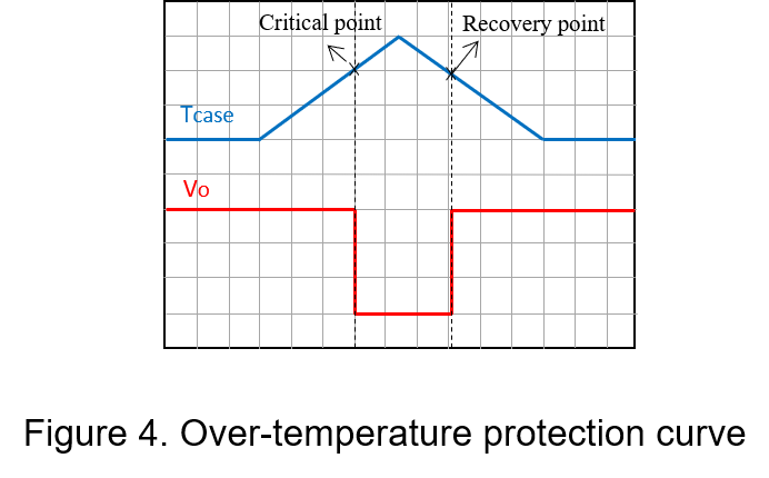
Regardless of internal temperature sensor or external temperature switch, when the converter casing reaches the specified temperature, the output voltage will be turned off immediately. At this time, the system can switch to other power-supplied equipment until the case temperature drops below the recovery value. The converter automatically returns on and behaves as shown in Figure 4.
Experimental
Functional introduction
The following table shows the specifications of the DC/DC power converter selected for this experiment.
| Power Converter | 3W, SIP8 package |
| Input Voltage | 4.5-9Vdc, Nom. 5Vdc |
| Output Voltage | 12Vdc |
| Output Current @full load | 250mA |
| Operation Temperature | -40~100°C |
The over-temperature protection action is to sense temperature, judge whether the temperature is too high, and then decide to shut down the converter if exceeds. In this experiment, the temperature switch is used to detect the case temperature, and the external resistor R4 is used to bias the control signal of power converter, and the resistor REST determines the temperature threshold. The system block diagram is as follows.

This experiment uses an integrated programmable resistor temperature switch, TMP708, which has an over-temperature protection function as the focus of this experiment. TMP708 has positive/negative temperature-related reference voltages and comparators inside.
Connect the resistor RSET which has 1% error between the SET pin and the GND pin of TMP708; OT pin is connected to the control pin of power converter, which determines the OT pin whether an inverter is needed to add according to logic action; the HYST pin allows the input hysteresis to be set at either 10°C (when HYST = VCC) or 30°C (when HYST = GND).
Power loss
Since the over-temperature protection circuit will increase additional power loss, which will be simply calculated including the power consumption of TMP708, bias circuit (R4 & SW) is

Then
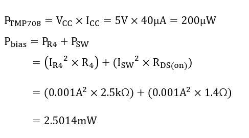
According to the total loss calculated by the above formula, the efficiency lost by the power converter is obtained

Measure waveform
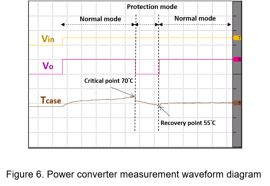
Figure 6 is the waveform of the power converter states the normal operation, and enters the protection mode, and then returns to the normal operation mode. It places the converter in a high-temperature environment. when input voltage startups to 5V firstly and then increases load current to 250mA gradually, the output voltage is still stable at 12V. At this time, the case temperature continues to rise until critical temperature is 70°C, the OT signal turns into a high voltage level and the control pin CTRL is pulled to the ground, the converter enters protection mode, so the output voltage drops to 0V. Next,
Moving the converter in cool-air environment, the case temperature drops rapidly until the recovery temperature is 55°C, the converter will automatically return to the normal operation mode from the protection mode, and then the output voltage rises to 12V.
Conclusion
The high-power converter uses an external temperature switch to effectively prevent the system in damage due to the continuous operation of power converter in over-temperature environment, so as to improve the reliability of the power converter. This article implements an over-temperature protection experiment, using a programmable temperature switch IC to reduce the complexity of circuit design and improve functionality, and finally combine with a power converter to realize the over-temperature protection function.
CTC is service provider for high-end power modules (DC to DC Converter and AC to DC Converter) for critical applications worldwide since 1987. We aim to be business generator and a virtual business unit. CTC is your own team with 35 years of experience for a strong business program from market research, product definition & development, supply chain management and total technical services.
CTC is the only corporation certificated with ISO-9001, IATF-16949, ISO22613(IRIS, AFNOR silver certificate), and ESD/ANSI-2020. We can 100% ensure not only the product, but also our workflow and service to match quality management system for every high-end application from the very beginning. From design to manufacturing and technical support, every single detail is operated under highest standard.