

You are here
Back to topWhat is Over Voltage Protection ?
In recent years, high reliability has become more important, in order to prevent the power converter from catastrophic failure, protection circuits exist necessarily. One of them is that output voltage stops rising continuously until above the safety threshold.
This article describes how to implement overvoltage protection for power converters, and introduces internal and external protection methods respectively. Finally, the measurement results confirm the importance of the overvoltage protection.
Introduction
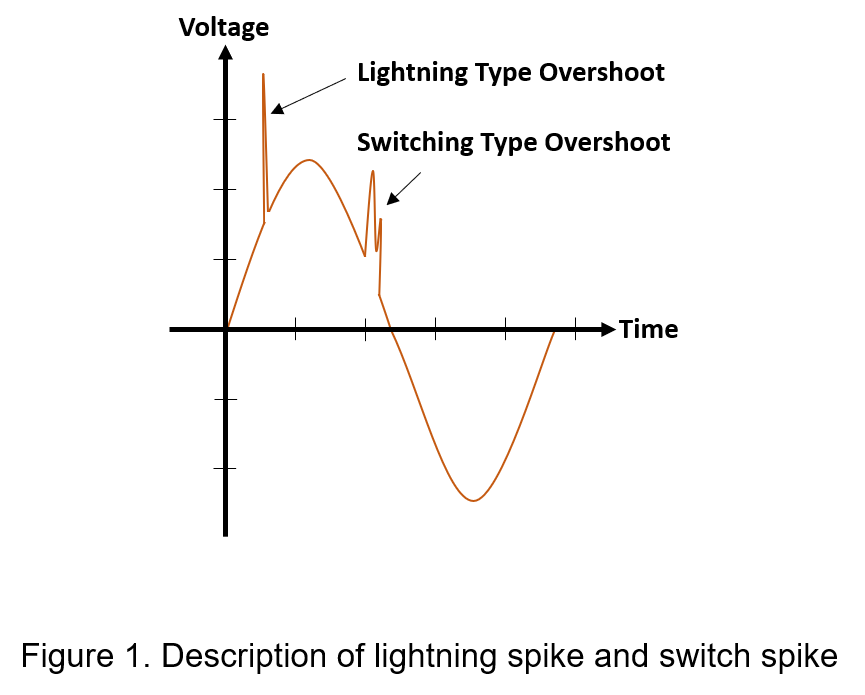
It is assumed that the input power supply is disturbed by large voltage spikes for many times, such as spikes generated by lightning; the other one is the spikes caused during the inductive switch turns on and off the high-power equipment. The spike voltage is superimposed on the original voltage, as shown in Figure 1.
If input voltage of the converter is frequently suffered by spikes, resulting in damage to internal devices and quick aging, and then affects the performance of converter. The output voltage exceeds the upper limit value for a period of time, which will cause energy accumulation to damage the back-end circuit and even lead the equipment to explode. Therefore, it is recommended that all power converters be designed with overvoltage protection.
Implementation of Overvoltage Protection
Overvoltage protection usually refers to protecting the power converter through specific circuit when the output voltage is too high. This method can be divided into internal and external protection. First, the internal protection action is used to detect the output voltage, determine that the voltage value is large enough, and then clamp the output voltage. To accomplish these actions, the simplest concept is to use a high precision comparator, resistors, bipolar transistor, and zener diode, as shown in Figure 2.
The negative feedback control loop of power converter has an overvoltage protection clamping circuit, which detects the output voltage and automatically turns on the clamping action when the output voltage rises uncontrollably.

If power converter itself has no overvoltage protection function, it can use zener diode, which is connected anode to negative terminal and cathode to positive terminal of the converter, respectively.
In design, most important thing is to evaluate the reverse zener voltage, which affects the clamp voltage.
If the zener voltage is too low, the output voltage of power converter is easily clamped. Hence, there is no way to adjust the output voltage through the internal negative feedback control or external trimming resistors; On the contrary, if the zener voltage is too high, the output voltage of the converter is clamped at abnormal voltage, causing high voltage drop to back-end circuit.
Therefore, the zener voltage must be slightly higher than the upper limit of the adjustable output voltage range, so that it still keeps protective function without affecting performance.

Measurement Results
Measurement environment of the internal overvoltage protection circuit is shown as Figure 4. Firstly, select a power converter with overvoltage protection function. It is feasible to use battery or extra power supply for the input power; the output of power converter is forced to be connected to another power supply. In addition, the power supply imposes an over-high voltage to simulate lightning spike or switching spike, and output terminal is connected to a multilayer ceramic capacitor. The purpose of the capacitor connected to the output terminal is to suppress noise, so the capacitance value doesn’t too large, mostly around 0.1µF~1µF. The measurement method is to use probe to measure both sides of the output capacitor, and oscilloscope graphically displays electrical signals and shows how those signals change over time.
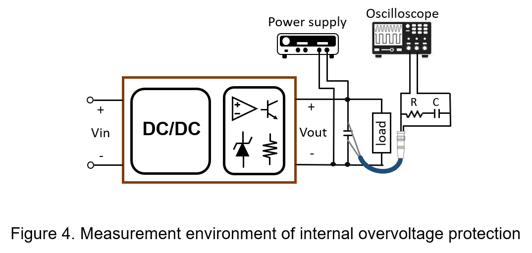
During measuring, the input voltage and load current remain unchanged, and the external power supply instantly supplies 20V high voltage to the output terminal, and then observes the clamping process of the output voltage waveform.
The following table lists the DC-DC power converter specifications for this measurement.
| Package | 1x1” |
| Input voltage | 9~36V, Nom. 24V |
| Output voltage | 12V |
| Overvoltage protection(typ.) | 15V |
| Efficiency (typ.) | 90% |
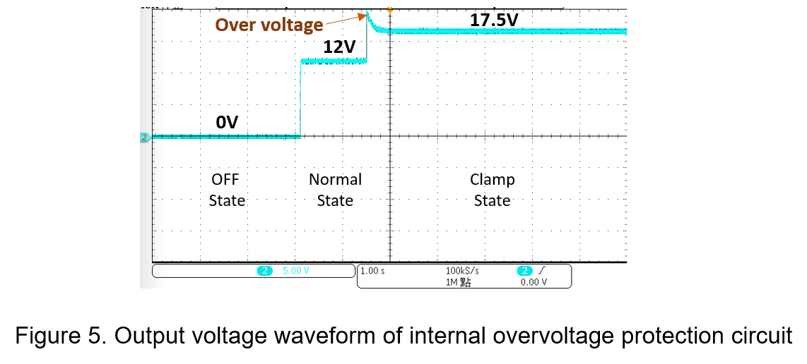
Figure 5 shows the waveform of output voltage, power converter acts from off state to normal operation state, and then enters the clamp protection state.
When imposing output voltage to reaches 17.5V, the clamp protection starts, and the output voltage is completely fixed at 17.5V, so it will not be in an uncertain state due to spike voltage.
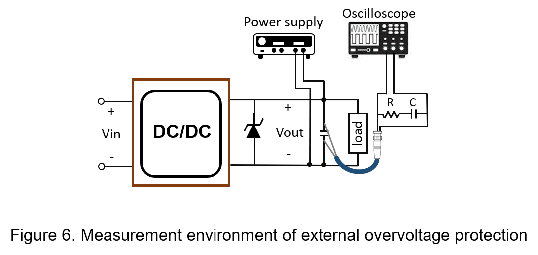
Another external overvoltage protection circuit measurement environment is shown in Figure 6. First, take a power converter without overvoltage protection.
The following table lists the DC-DC power converter specifications for this measurement.
| Package | 1x1” |
| Input voltage | 9~36V, Nom. 24V |
| Output voltage | 15V |
| Overvoltage protection(typ.) | N/A |
| Efficiency (typ.) | 89% |
An external zener diode is connected to the output terminal, and the anode is connected to the negative terminal of the converter; the cathode is connected to the positive terminal of the converter.
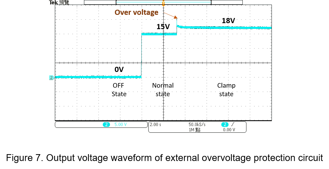
Maximum output voltage of the power converter by trimming is 16.5V, so it can select the appropriate zener voltage 18V. The power supply also instantly supplies 20V high voltage to the output terminal, and observe whether the output voltage can be clamped at the zener voltage level. The external power supply also instantly supplies 20V high voltage to the output terminal, and observe whether the output voltage can be clamped at the zener voltage level.
The output waveform of the power converter is shown in Figure 7. When the power converter in normal state, high voltage is imposed on the output terminal to make the zener diode enter the breakdown region and the output voltage is clamped at the zener voltage level.
Conclusion
Power converters must prioritize safety regardless of the applications. Whether internal or external overvoltage protection, the clamping voltage value is closely related to the selection of the zener diode. Therefore, selecting appropriate devices in design is to obtain more substantial protection.
CTC is service provider for high-end power modules (DC to DC Converter and AC to DC Converter) for critical applications worldwide since 1987. We aim to be business generator and a virtual business unit. CTC is your own team with 35 years of experience for a strong business program from market research, product definition & development, supply chain management and total technical services.
CTC is the only corporation certificated with ISO-9001, IATF-16949, ISO22613(IRIS, AFNOR silver certificate), and ESD/ANSI-2020. We can 100% ensure not only the product, but also our workflow and service to match quality management system for every high-end application from the very beginning. From design to manufacturing and technical support, every single detail is operated under highest standard.