

You are here
Back to topThe Effects of Using Filter on Power Converter
The power converter converts AC voltage into DC voltage, but the AC component called ripple in the DC voltage cannot be completely eliminated, which causes the instability of the system. Using the filter can suppress ripple and improve overall system accuracy.
This article will describe common filter architectures, and the measurement results adding the filter to the power converter.
1. Filter Architecture
The filter is used to completely pass the signals in a specific frequency range and quickly attenuate the signal in other frequency. It means that the circuit uses the filters to suppress the interference noise and retain the wanted signal. The common low-pass filter composed of capacitors and inductors reduces the electromagnetic interference on the copper foil wire of the printed circuit board and the high-frequency noise on the resonant wave. Here are some common low-pass filter architectures.
- Capacitive-type filter
A capacitor is connected in parallel between the input power supply terminal of the power converter and the ground. The basic principle is that the impedance of the capacitor decreases when the frequency increasing. Therefore, high-frequency signal can be bypassed directly to the ground without affecting the power converter, as shown in Figure 1.
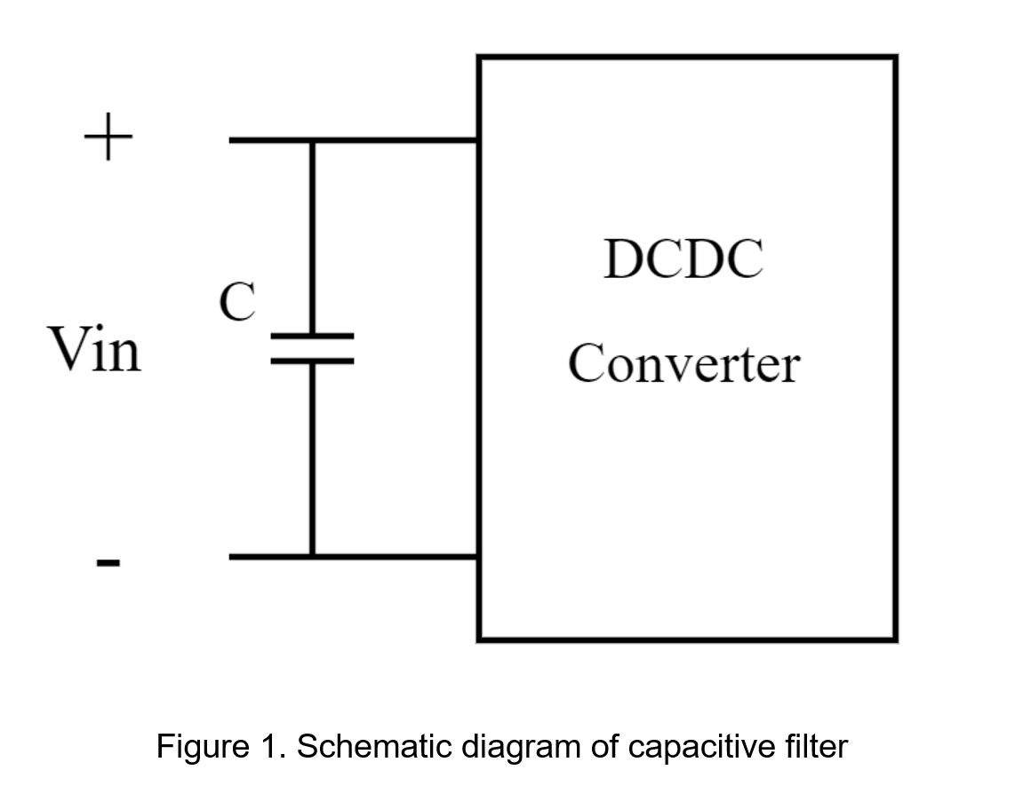
The different material of capacitors also affects the filtering characteristic. For example, the volume of electrolytic capacitors takes up a lot of space on the printed circuit board, but has higher withstand voltage and the larger options range of capacitance; the selected capacitance and withstand voltage range of ceramic capacitors has smaller, but the advantages are lower ESR than other types and small size.
- Inductive-type filter
An inductor is connected in series between the input power supply terminal of the power converter and the power converter. The basic principle is to use the impedance of the inductor increases when the frequency increasing, so that the high-frequency signal path is disconnected and does not affect the power converter, as shown in Figure 2.
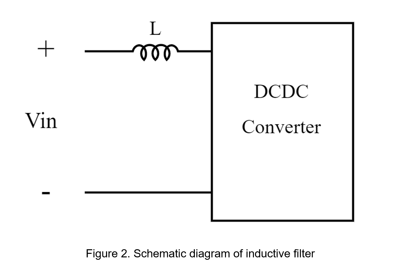
Inductive filters are suitable for high current applications. If it is used in a high current condition, the voltage drop of the components will cause the output voltage to decrease. Therefore, the output voltage using the inductive filter is slightly smaller than that of the capacitive filter.
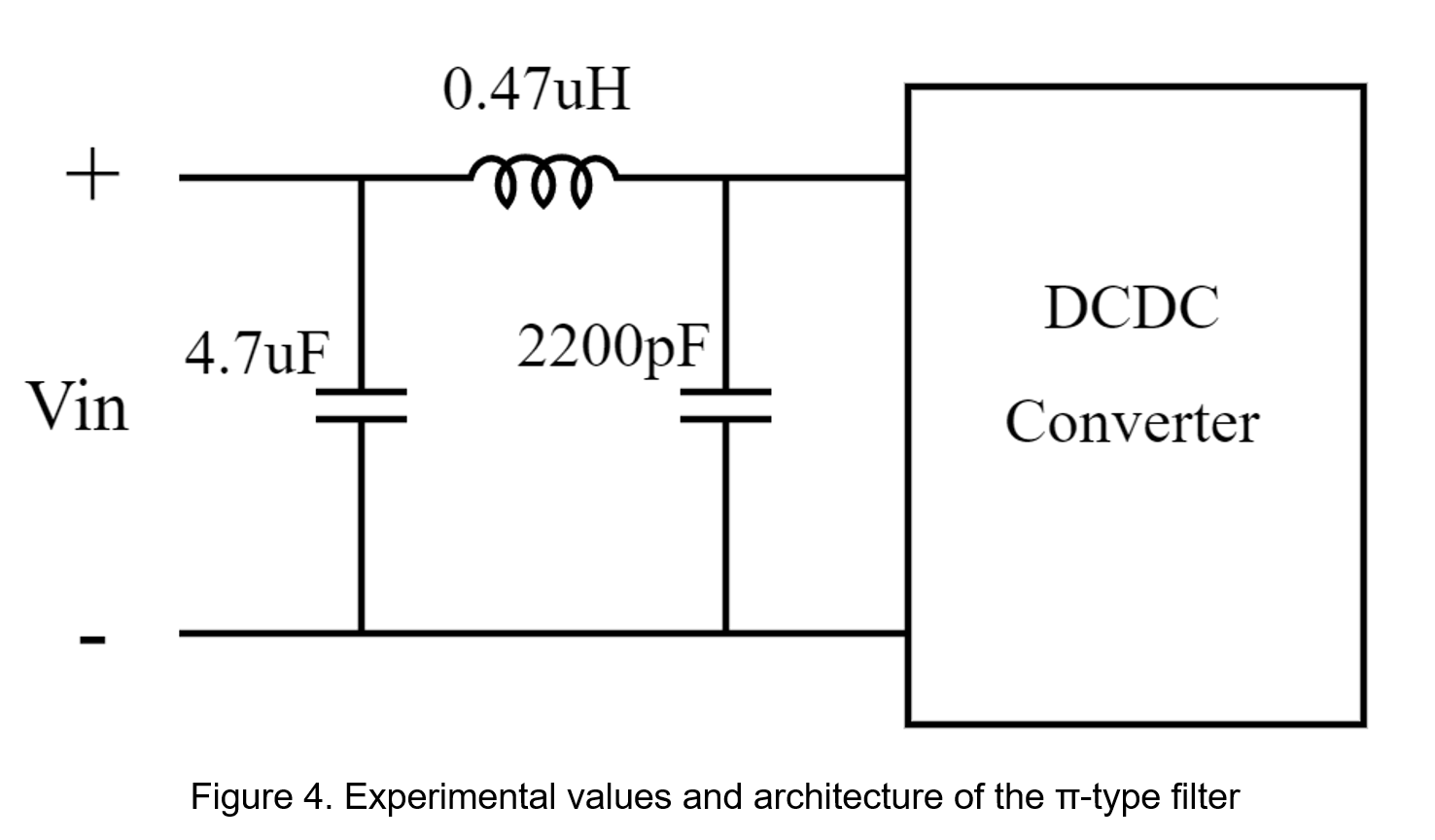
- π-type filter
An inductor (L) is connected in series between the input power supply and the input of the power converter; a capacitor (C1) is connected across the input of power supply terminal and ground; the other capacitor (C2) is connected across the input of the power converter and ground.
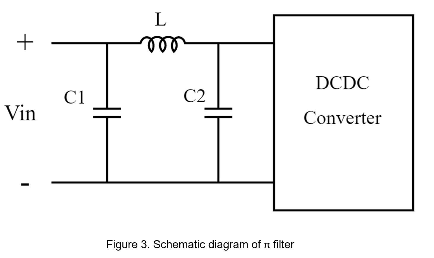
Compared with the two architectures, the π-type filter is a two-stage filter, where the capacitor (C1) and the inductor (L) are regarded as the first-stage low-pass filter, which can filter out most of the AC components, and then using bypass capacitor (C2) can filter high-frequency noise. In design, once the noise frequency exceeds the corner frequency of the π-type filter, it will be rapidly attenuated, so the values of inductor and capacitor are designed according to different frequency range requirements.
- For low-pass filter design
There are switching elements inside the power converter. During the switching process, the switching noise is likely to be generated to couple to the secondary measurement through the transformer. It can be seen that the frequency of the noise will be filtered is about the operating frequency of the power converter. The capacitance and inductance values are designed by formula (1).
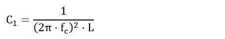
C1 and L are capacitance and inductance in low-pass filter respectively, and fc is the operating frequency of power converter
- For bypass capacitor design
Bypass capacitor mainly is used to filter out AC noise, and it is suitable to select capacitor which has low equivalent series resistance, and designing the resonant frequency to be close to the switching frequency. In addition, it is important to avoid selecting too large capacitance to generate inrush current.
2. Experiment
Using low-pass filter in power converter can change the negative feedback gain and phase in system, which further affects the transient response, switching time, and even causes oscillation or abnormal function. Therefore, the specifications of power converter should be evaluated before designing filters.
| Output power | 40W |
| Input voltage | 9-36Vdc, Nom.24Vdc |
| Output voltage | 5Vdc |
| Heavy load current | 8A |
| Conversion efficiency | 89% |
| Operation frequency | 350kHz |
The operation frequency of the power converter is 350kHz which is closed to the main noise frequency. The half-power point of the π-type filter is designed at 1/10 of the operation frequency to achieve the purpose of attenuating high-frequency noise. Set firstly the low-pass filter capacitor (C1) to 4.7µF, and calculate the inductance value as follows.
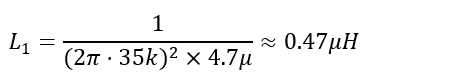
A bypass capacitor of 2.2nF is used to filter out higher frequency noise.
According to the above filter types, all the experimental data are made into a graph with different capacitance or inductance values for testing as follows.
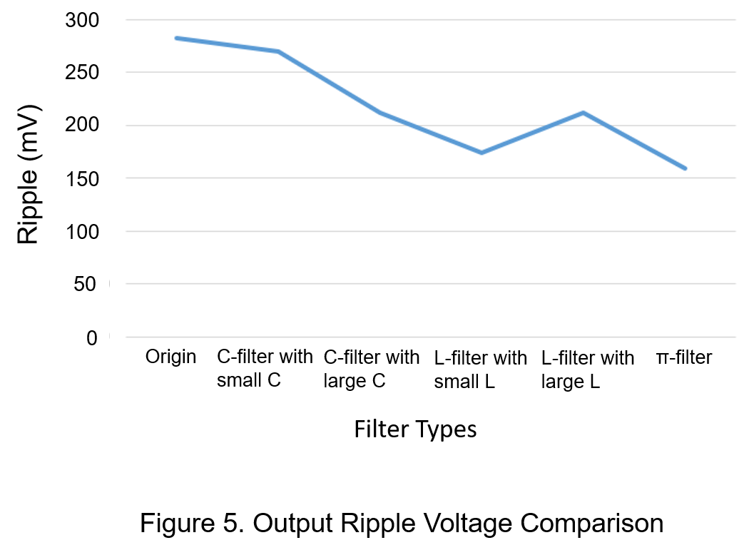
From figure 5, it can be observed that after adding filters, the output ripple voltage is effectively reduced. Even the same type of filter is subject to different components, and then the degree of ripple suppresses varyingly.
3. Conclusion
This article briefly introduces the different architectures of filters, and how to design the appropriate capacitance and inductance values of the low-pass filter for decreasing the high-frequency noise. Finally, the experimental results show that the π-type filter is the most effective to filter out high frequency noise from power converters.
CTC is a professional service provider for high-end power supply modules (AC to DC Converter and DC to DC Converter) for critical applications worldwide since 30 years. Our core competence is to design and deliver products with leading technologies, competitive pricing, extremely flexible lead-time, global technical service and high-quality manufacturing (Made In Taiwan).
CTC is the only corporation certificated with ISO-9001, IATF-16949, ISO22613(IRIS), and ESD/ANSI-2020. We can 100% ensure not only the product, but also our workflow and service to match quality management system for every high-end application from the very beginning. From design to manufacturing and technical support, every single detail is operated under highest standard.