

You are here
Back to topReflow Technology
The electronic industry is developing rapidly, and surface mount technology is undoubtedly an important invention to promote its growth. However, wave soldering is no longer suitable for surface components decreasing volume. Therefore, reflow soldering technology came into being. This article will introduce reflow soldering technology, analyze various temperature curves, and common problems.
1. Introduction
The standard of reflow soldering temperature curve refers to IPC/JEDEC J-STD-020E. In practical applications, it must be adjusted according to product specifications and production environment. Exceeding the product specification may cause damage, so reflow soldering must be tested correctly before putting it into use.
The electronic industry is developing rapidly, and surface mount technology is undoubtedly an important invention to promote its growth. However, wave soldering is no longer suitable for surface components decreasing volume. Therefore, reflow soldering technology came into being. This article will introduce reflow soldering technology, analyze various temperature curves, and common problems.
- Reflow Soldering
Reflow soldering is to use solder paste to bond electronic components to solder pads, and control the temperature through the reflow oven, solder paste is gradually melted, and then the printed circuit board is cooled and solder solidified to achieve permanent bonding.
This is a common method used in surface mount technology to bond components, which saves large amount of solder, and more suitable for surface mount device.
- Solder Paste
This is a material used to solder electronic components to printed circuit board, and functions like tin-wire and tin-powder. The solder paste is a mixture of flux and tin powder, which is characterized by its viscosity when no soldered, and can stick to the components placed on the surface of the printed circuit board, protecting the surface elements from being slightly shaken and not being offset. So the main purpose is to completely fix surface mount device on the printed circuit board by reflow soldering.
2. Reflow Temperature Curve
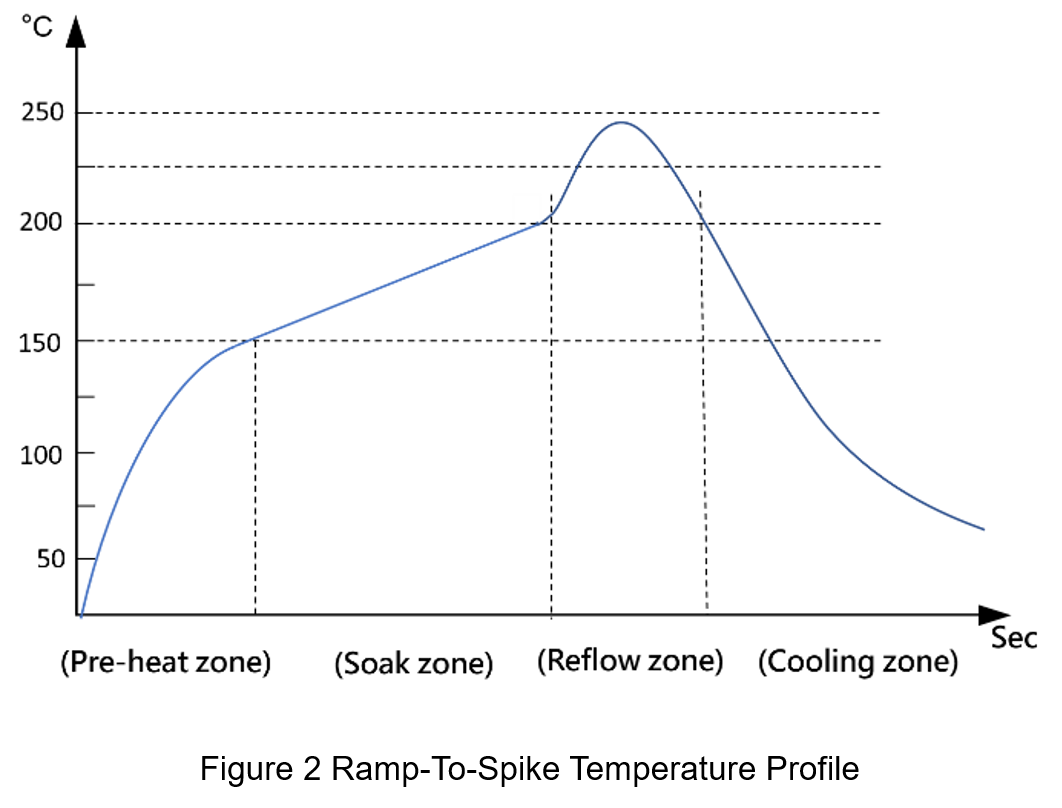
Common reflow soldering temperature curves include Ramp-Soak-Spike (RSS) and Ramp-To-Spike (RTS), as shown in Figure 1 and Figure 2, which can be divided into four stages, the preheat zone, soak zone, reflow zone and cooling zone, the following will introduce four stages one by one.

- Preheat Zone
This area is the stage where the temperature of the Printed Circuit Board Assembly (PCBA) raises from normal temperature to 150°C, mainly to allow the printed circuit board and surface mount device components to be gradually preheated to avoid damage during soldering. In this stage, the volatile solvent in the solder paste will slowly evaporate, and the preheating time depends on the allowable maximum rate of the surface components temperature changing and the solvent volatility of the solder paste.
- Soak Zone
The temperature of RSS usually maintains in the region of 150±10°C, and the temperature of RTS falls between 150-190°C. When the solder paste is on the eve of melting, the volatiles is further removed, and the activator will start to act, decomposing oxides on the welding surface. The important role of this area is to maintain a uniform temperature of surface components even though different sizes and materials, so that the PCBA can reach thermal equilibrium before entering the reflow zone.
- Reflow Zone
The reflow zone is the area with the highest temperature during the reflow soldering process, also known as the Time Above Liquids (TAL), and the temperature is mostly set to be 20-40 °C higher than the solder liquefaction temperature. Components need to stay in the reflow zone for long time enough to wet the solder joints, but if the time too long, devices will be damaged.
- Cooling Zone
After the reflow zone, the product undergoes a cooling process, calling the cooling zone, which mainly strengthens the solder joints. Although it is possible to allow the PCBA to cool in air, it is better to use a temperature control system to control the cooling rate, because the cooling rates too fast may damage components or solder joint peeling; Slowly cooling will produce tin-silver-copper-nickel intermetallic compounds and reduce the strength of solder.
3. Selection of Reflow Profile
The common reflow curve has two kinds of Ramp-Soak-Spike(RSS) and Ramp-To-Spike(RTS), the most important difference point falls in the soak zone, the following brief introduction of the two curves.
- Ramp-Soak-Spike Temperature Profile
In PCB, if the components in high-density directly enters reflow zone by skipping the soak zone, or the spacing between the PCBA is too dense during mass production, the soldering defects will easily occur during reflow. Because the rate of heat absorption of various types of surface elements is inconsistent, RSS temperature curve is required.
Setting the soak zone in RSS temperature curve setting is to achieve temperature balance between the solder pads on the PCB and solder pads of various components as much as possible before entering the reflow zone, as so to achieve the best soldering.
- Ramp-To-Spike Temperature Profile
With the progress of reflow soldering technology, many reflow oven also has thermal compensation, which enables the temperature difference between components to be controlled within a certain range, and then RTS temperature curve can be used.
In the application, it is necessary to care whether the temperature of each position on the PCBA before entering the reflow zone is consistent, and determine the test correctly before using. In order to avoid the situation of non-stick tin and poor soldering.
4. Common Defects in Reflow Soldering
In the reflow process, the temperature controller is a very important part. If the temperature nonuniformity happens, it easily causes many problems. The following will explain various undesirable phenomena and their causes.
- Tin Beads, Tin Balls
This phenomenon is easy to occur in the case of heating up fast, the rapidly volatilized gas in the solder paste will be taken out together with solder paste, so that the solder paste separated during the soldering will melt and gather, and those located under the surface component gap are called solder balls. And the splash out is called tin ball..
- Head-In-Pillow
The main reason for the head-in-pillow (HIP) may be due to the Wick effect because of the long preheating time, which causes excessive oxidation of the solder. The improvement method is that reducing reflow zone time.
- Tombstone
This phenomenon is caused by the difference in wetting time between the two sides of the component during reflow soldering. There are many ways to improve the effect. One of them is to slow down the heating rate of soldering so that the temperature of component sides reaches thermal equilibrium before the melting point, or choose high viscous solder paste. It depends on the design of the pad on the PCB to improvement. When the size of the pad at both ends of the component is different or asymmetrical, it is more likely to cause tombstones and skew.
5. Conclusion
With the development of surface-mount welding technology gradually matured, reflow soldering is more suitable for the shrinking SMD components. Many defects in reflow soldering technology in production are caused by improper temperature control. Therefore, in reflow soldering application, the control of temperature will greatly affect production.
CTC is a professional service provider for high-end power supply modules (AC to DC Converter and DC to DC Converter) for critical applications worldwide since 30 years. Our core competence is to design and deliver products with leading technologies, competitive pricing, extremely flexible lead-time, global technical service and high-quality manufacturing (Made In Taiwan).
CTC is the only corporation certificated with ISO-9001, IATF-16949, ISO22613(IRIS), and ESD/ANSI-2020. We can 100% ensure not only the product, but also our workflow and service to match quality management system for every high-end application from the very beginning. From design to manufacturing and technical support, every single detail is operated under highest standard.