

You are here
Back to topThe effect of convection wind on the power converter
The developers of power converters are all devoted to the technology related to heat dissipation design nowadays. So, how to meet the requirements of long-term power supply operation and wide operating environment temperature range are all future research directions.
This article describes how to perform accurate temperature measurements on power converters using thermocouple temperature lines and infrared thermal imaging cameras, introduces related precautions and techniques, and analyzes the temperature behavior of power converters with different convective winds.
1. Introduction of vertical closed loop wind tunnel
In order to simulate various wind speed environmental test conditions, the vertical closed-circuit wind tunnel machine can set the temperature automatically or manually, and the common wind speed range is 0.1m/s~5m/s. Place the power converter in the inner cavity to test the temperature of each point, and its dimension is 30cm*30cm*50cm. Figure 1 is a top view and a front view of the inner cavity of the loop wind tunnel.
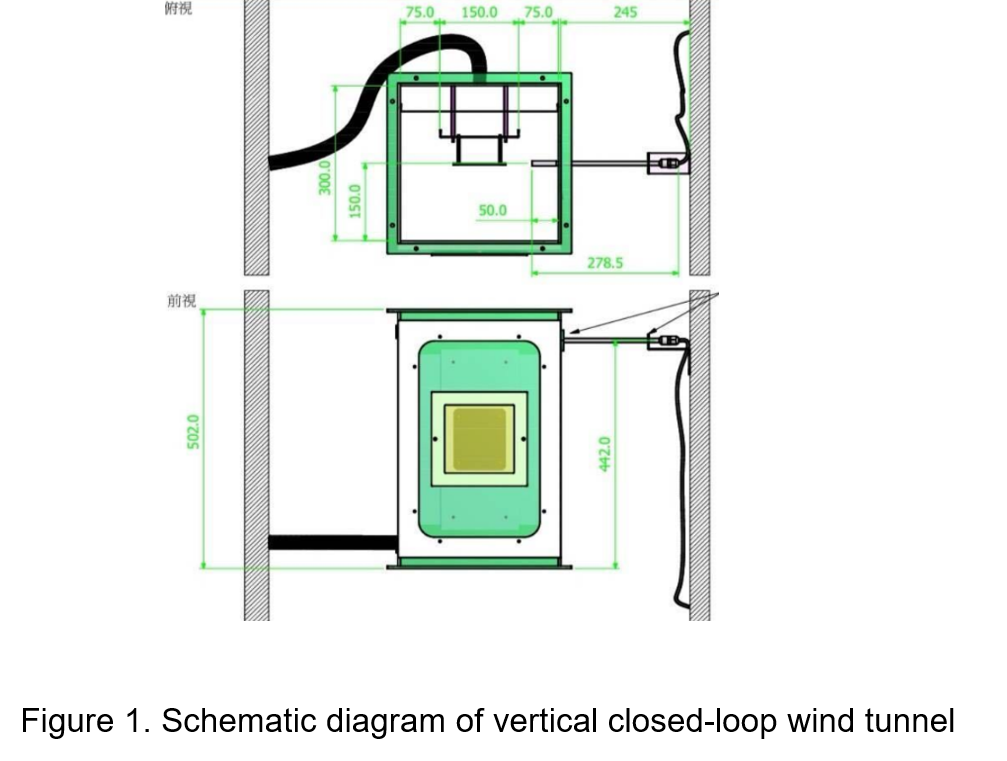
Through the front window, use an anemometer to measure the wind speed around the power converter installed in the inner cavity through the pearl plate. This anemometer can be externally connected to a personal computer to display the real-time wind speed. Two methods of measuring temperature will be described.
- Thermocouple temperature
Thermocouple is a common temperature measuring element, its principle is that two different components of material conductors form a closed loop. When there is a temperature gradient at both ends, a current will flow through the loop. Thermoelectromotive force, this is the Seebeck effect.
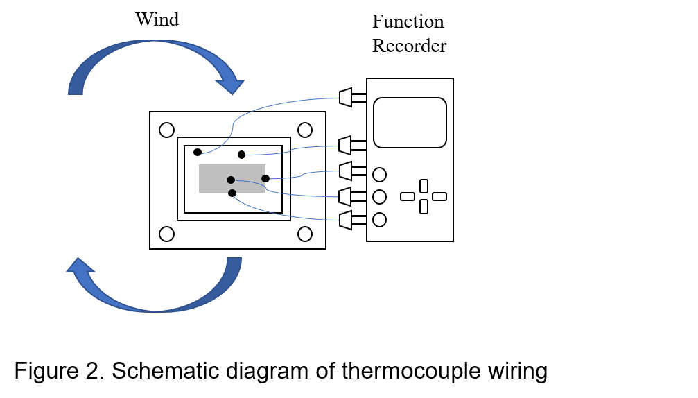
The thermocouple temperature sensor is directly attached to the printed circuit board and the power converter, and the temperature signal of the measured object is converted into a thermoelectric force, then converted into a temperature signal through the multi-function recorder. Through these temperature data, the operating temperature range of the product can be defined or a derating curve can be drawn.
- Infrared thermal imaging camera
The components on each circuit board are different in circuit design and circuit layout, resulting in different heat accumulation and heat dissipation. The infrared thermal imager can provide users with an infrared heat map to quickly analyze the overall temperature distribution of the printed circuit board, as shown in Figure 3 :
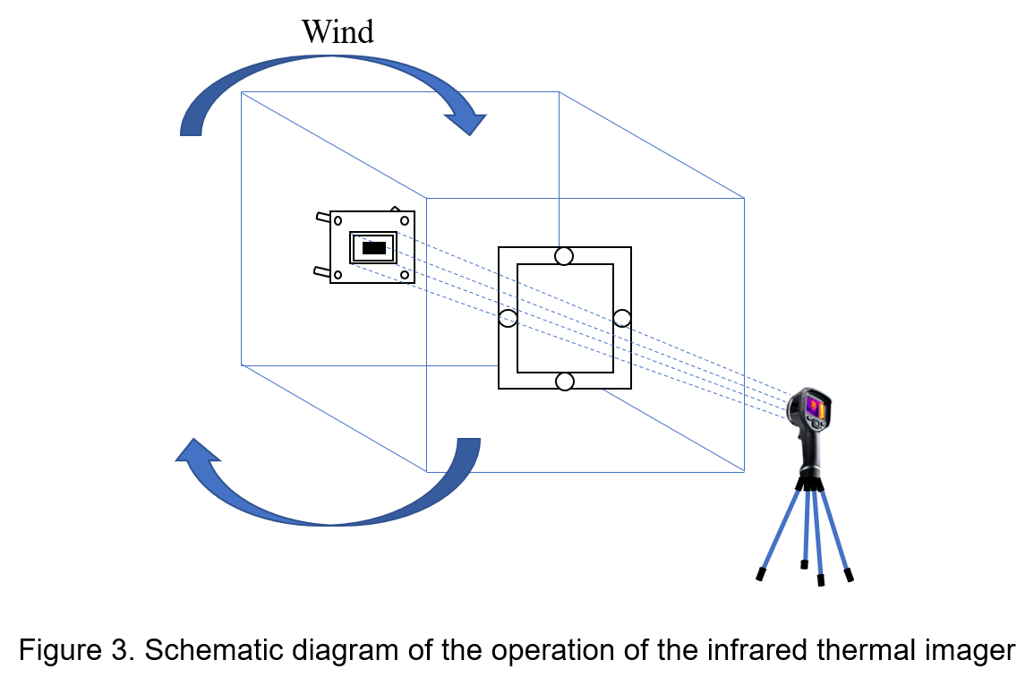
The infrared thermal imaging camera holder is placed outside the inner cavity of the vertical closed-circuit wind tunnel. In order to improve the transmittance of infrared rays, the optical film is coated on germanium laminated glass to improve the transmittance and protect the surface. The LCD screen of the infrared thermal imager clearly displays the image of the entire temperature field distribution of the printed circuit board and all components and accurate temperature measurement. The data can be input into the computer software in real time through the USB connector for analysis, storage and monitoring.
2. The effect of convective wind
The heat generated during operation can cause the internal temperature of the power converter rise rapidly. If the heat energy is not dissipated in time, the equipment will continue to heat up, and the components will overheat and fail. Therefore, it is very important to perform better heat dissipation treatment for high temperature components. Depending on the specific characteristics of the component, different environments and cost considerations, the most commonly used method of heat dissipation is air flow. In terms of design, micro-fans are placed near high-temperature components, such as power converters with high output power. This method is to forcibly increase convection air, so only low additional power is required to achieve high operating temperature range, reduce thermal resistance and improve printed circuit. power density of the board.
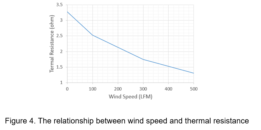
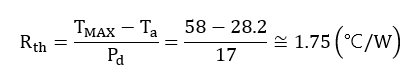
Taking the wind speed of 300LFM as an example, when the load current of the power converter is measured at 10A, the power loss is 17.1W, the ambient temperature measured by the thermocouple temperature line is 28.2°C and the maximum surface temperature is 58°C. The power supply is calculated according to the thermal resistance formula to know converter-to-air thermal resistance Rth:
It can be seen from Figure 4 that the thermal resistance varies with wind speed conditions. The higher the convective wind speed, the more cold air can pass through the surface of the power converter to remove heat, and the thermal resistance gradually decreases.
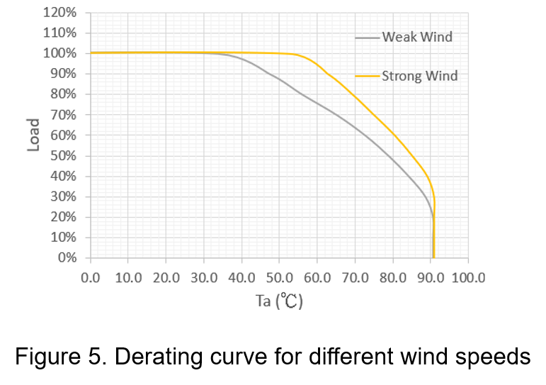
As Figure 5, when the power converter is allowed to perform full load from weak wind to strong wind environment, the maximum ambient temperature is increased from 35°C to 55°C; in addition, at the same operating temperature of 60°C, the maximum load is greatly increased from 75% to 96%.
In order to utilize the natural convection air to dissipate heat effectively, several high-temperature components are distributed on the printed circuit board to keep the surface temperature of the printed circuit board consistent. Most of the high-temperature components are placed at the center of the printed circuit board rather than at the corners, and components with a higher height cannot be mounted around to block the natural convection wind to reduce the heat dissipation effect.
3. Conslusion
Temperature control is an important factor in improving the reliability of power converters and the operating ambient temperature range. Nowadays, the heat dissipation methods applied to printed circuit boards are diversified, among which the heat dissipation method of enhancing convection air is more economical and can achieve good heat dissipation effect.
In circuit applications, the use of thermocouple thermometers or infrared thermal imaging cameras to monitor the temperature of electronic components can analyze the overall temperature distribution more effectively. By sorting out the experimental data of different wind speed conditions, users can better understand the relationship between wind speed and thermal resistance.
CTC is a professional service provider for high-end power supply modules (AC to DC Converter and DC to DC Converter) for critical applications worldwide since 30 years. Our core competence is to design and deliver products with leading technologies, competitive pricing, extremely flexible lead-time, global technical service and high-quality manufacturing (Made In Taiwan).
CTC is the only corporation certificated with ISO-9001, IATF-16949, ISO22613(IRIS), and ESD/ANSI-2020. We can 100% ensure not only the product, but also our workflow and service to match quality management system for every high-end application from the very beginning. From design to manufacturing and technical support, every single detail is operated under highest standard.