

You are here
Back to topWhat is derating curve of DC/DC converter?
In many kinds of common applications, the design of power converters needs to consider thermal issue, if not, thermal energy accumulation will cause components (such as inductors, MOSFETs, transformers) to exceed the maximum operating temperature, and it will result in reduced component reliability or premature failure. In order not to over the maximum temperature limit of the power converter, it is necessary to know the safe operation area the power converter can work from the derating curve, and also define the upper limit of the load.
This article explains the reliability analysis of the derating curve, and evaluates whether the power converter can operate normally from the experimental results.
1. Derating curve
Industrial power applications are mostly used severe environment, as the need for system miniaturization, the heat dissipation problem of the power converter must be properly arranged in the limited space application.
Figure 1 clearly shows the load current corresponding to the power converter at different ambient temperatures. As shown in the figure, under defined convection condition, the output load, and the operating temperature. Therefore, the derating curve is enclosed in a polygon.
The area within the curve is called the Safe Operating Area (S.O.A), which is used to confirm whether power converter can work in safe conditions, that is, as it is safe to work within S.O.A. area, conversely it is possible to exceed S.O.A. area will cause damage to the components.
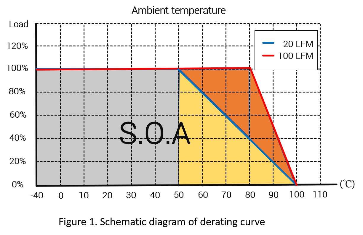
As the ambient operating temperature increases, the additional heat accumulated inside the power converter because of larger thermal resistance cannot be quickly conducted from the power converter to the air , which will cause the overall conversion efficiency to become worse and generate more heat until power converter take place thermal runway. To avoid this, the operating load must be reduced to maintain operation.
As shown in figure 1, when the wind speed is 20 LFM, the power converter can operate at full load from -40°C to 50°C. Once the ambient temperature exceeds 50°C, the allowed output load must be reduced, as shown in the yellow area. For example, in the ambient temperature is 80℃, the output load can't over than 40% of the full load. The temperature range of full load with wind speed 100 LFM is -40~80℃ is larger than the temperature range of -40~50℃ of full load with wind speed 20 LFM.
Therefore, using larger convective airflow to dissipate heat from the power converter can increase current load and improve the range of ambient maximum operating temperature.
2. Experiments and tests
Thermocouple sensors are used in this experiment, and the thermocouple sensors are respectively fixed on the center point, long side, short side of power converter package, PCB input, and ambient temperature, etc. And the measurement distance of ambient temperature is about 3 cm from the power converter to thermocouple.
Figure 2 is a schematic diagram of the measurement environment of the power converter in simulating the no airflow.
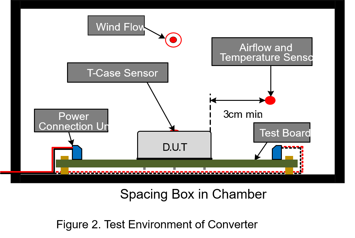
The power converter is placed in a closed-loop circulating wind tunnel, and then simulates different wind speeds and compares the relationship between thermal energy of the components and the maximum output load. Two experiments are used to illustrate the influence of convective wind speed and heat sink on the derating curve respectively, and then the graphs are drawn and explained.
- Experiment 1: Effects of different wind speeds for the derating curve
The specifications of the power converter are as following:
| Input voltage | 12Vdc |
| Output voltage | 5Vdc |
| Output current (full load) | 12A |
| Baseplate temperature limit | 120℃ |
Maximum operation ambient temperature as the horizontal axis; output load percentage as the vertical axis. Record the experimental data of input power, output power and the temperature value of each thermocouple,and t is shown as a graph after statistics.
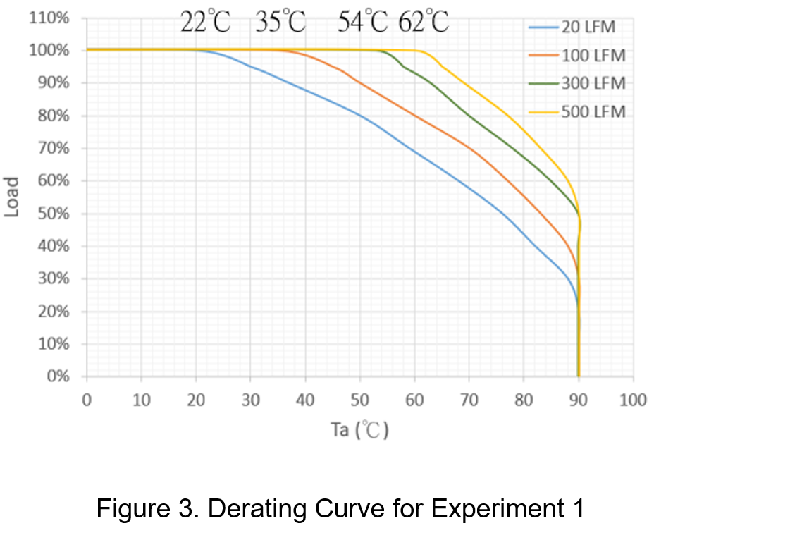
As shown in Figure 3, the derating curve varies with the different wind speed conditions, and the derating curve corresponding to the specific design must be checked. In full load condition, when the wind speed is 20LFM, 100LFM, 300LFM and 500LFM, the maximum operating ambient temperatures are about 22°C, 35°C, 54°C, and 62°C, respectively. That is to say, higher the wind speed can take away the more accumulated heat from the power converter which means to get the smaller the thermal resistance and the larger ambient temperature range can be accepted.
In addition, in wind speed 20LFM condition, the power converter provides about 56% of the maximum load when operating temperature in 70°C. Increasing the wind speed to 500LFM can provide about 88% of the maximum load, which means that the larger wind speed can improve the maximum load.
- Experiment 2: Effects of heat sink for the derating curve
When using the power converter with high power consumption or nearly heating elements, the heat dissipation intensity should be strengthened in design. One method is to install a cooling fan, and the disadvantage is to consume more power consumption and add unpredictable noise. Another better method to expand the heat dissipation area, such adding a fin-shaped heat sink on the surface of the power converter package. Usually the heat sink or the base plate of power converter will be separated by thermally conductive glue to increase the insulation distance to avoid insulation failure, and fill the gap between the two metal media through the glue to avoid poor contact.
Using another power converter to test the effects of heat dissipation from the heat sink. The specifications of the power converter are as following:
| Input voltage | 24Vdc |
| Output voltage | 12Vdc |
| Output current (full load) | 12.5A |
| Baseplate temperature limit | 105℃ |
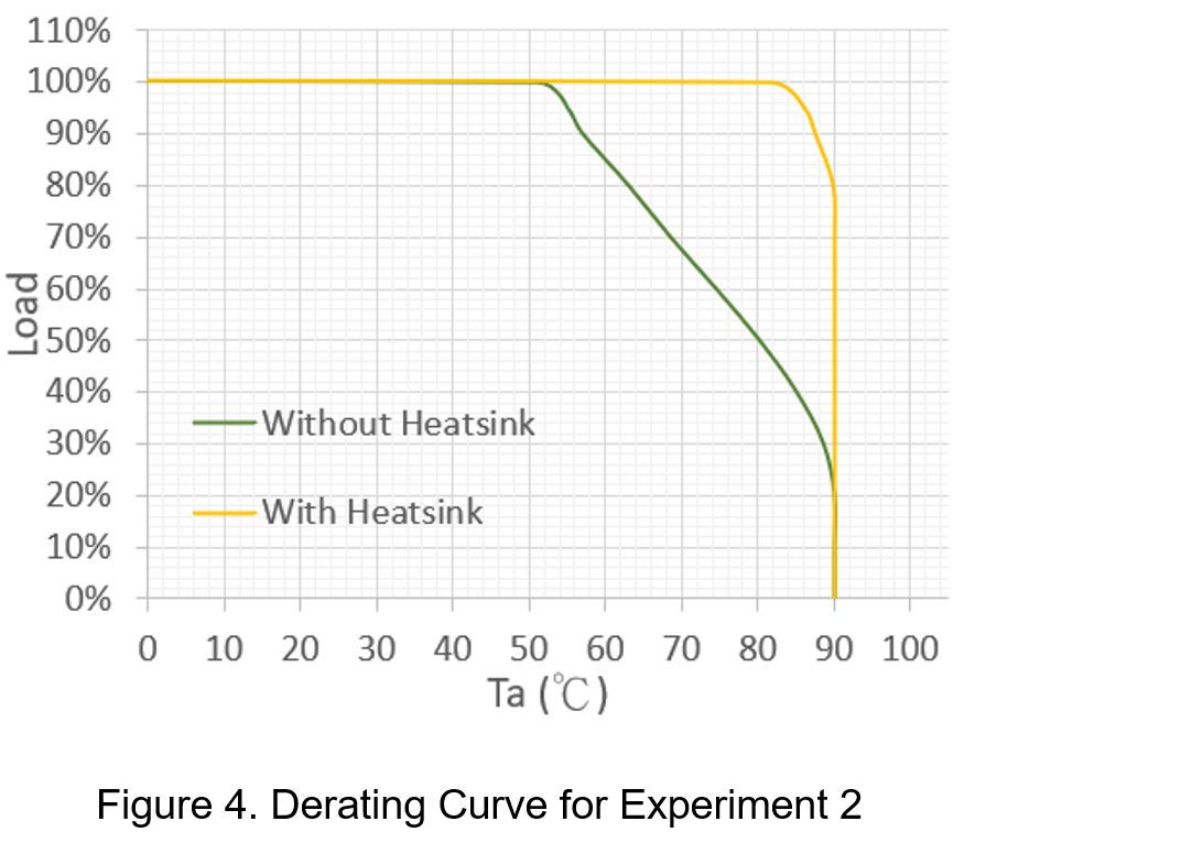
It can be seen from Figure 4 that this analysis has a maximum ambient temperature increased from 52°C to 84°C at full load compared to power converters without heat sink; In addition, at the same operating temperature of 70 °C, the maximum load greatly increases from 68% to 100% for heat sink case.
From the experimental results, the heat sink has a large advantage on the temperature range and maximum load of the power converter at full load. In a convection-free environment, planning to attach heat-generating components (such as CPU and MOSFET) to the system metal case is also a method to help dissipate heat.
Using heat sink is a method with good heat dissipation effect and less effect on the system.
Conclusion
For different applications, power converters must focus on the thermal energy performance. Good heat dissipation can improve the time limit and reliability of the power converter
From the experimental results, it is understood that the heat dissipation capacity is proportional to the maximum load and ambient operating temperature range.
CTC is a professional service provider for high-end power supply modules (AC to DC Converter and DC to DC Converter) for critical applications worldwide since 30 years. Our core competence is to design and deliver products with leading technologies, competitive pricing, extremely flexible lead-time, global technical service and high-quality manufacturing (Made In Taiwan).
CTC is the only corporation certificated with ISO-9001, IATF-16949, ISO22613(IRIS), and ESD/ANSI-2020. We can 100% ensure not only the product, but also our workflow and service to match quality management system for every high-end application from the very beginning. From design to manufacturing and technical support, every single detail is operated under highest standard.