

You are here
Back to topHow do you parallel two DC/DC converters?
Aug 11, 2020
In the market, most power converter products are not designed for parallel applications. Nowadays, the demand for power is gradually increasing. Therefore, using multiple powers in parallel to increase the overall power will save redesign time. However, it has to have a good current sharing control method. This article will introduce the advantages and disadvantages of traditional current sharing methods, and also choose the current sharing controller to achieve the parallel connection and current sharing of power converters.
Introduction
Industrial manufacturing is gradually toward the automation industry, and smart factories have become a global trend. Equipment such as robotic arms and industrial servers required for automated production and digitization have high power requirement. In addition, in terms of railway applications, train control systems and computers, etc., all require a power supply of more than 150W. Science and technology develop rapidly, in addition to the basic requirements of safety and reliability, the selection of power supplies must meet the high-power output conditions. In order to increase the power of the converter, besides the circuit design that include upgraded the components and functions of the power converter, it is also possible to use two power converters in parallel. It doesn't need to redesign new products, and directly obtain greater power, which is a way to save design time and cost. The advantage is that each module bears smaller current and the selection of components is more flexible. In case one of the power supplies fails, the other one can be backup power and maintained the output voltage. It can be maintained and replaced for increasing the overall reliability of the power systems.
However, if the two power converters are directly connected in parallel, they have unbalanced output currents even two power supplies of the same specification. Long-term use on this situation will shorten the life of the power converters and cause reliability problems. There are quite a lot of parallel schemes so far, and the main methods are divided into two categories, voltage droop method and active current sharing. This article will introduce the advantages and disadvantages of passive and active current sharing, and study the way of an active current sharing. Finally, an active current sharing test board is made for achieve parallel current sharing with two 40W DC/DC converters
Parallel circuit
Introduction to parallel
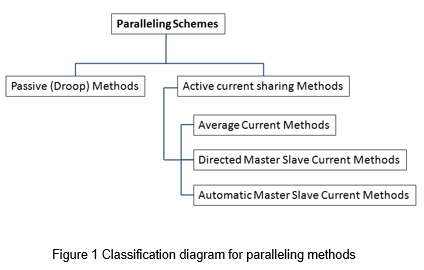
The ideal characteristic of a parallel power supply system is that each power module shares the load current stably and equally. There are two categories: passive and active current sharing. And active current sharing methods can be divided into three types, average current method, directed master-slave method and automatic master-slave method.
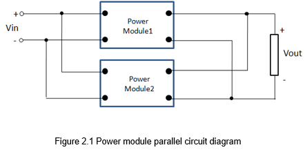
Since each power module has a tolerance, if they are directly connected in parallel without taking measures that evenly distribute the current for the power modules, It will cause the output load unbalanced, as shown in Figure 2. The power converter with higher output current will bear greater stress, and long-term used will reduce the life of the power module. Or the current limit is trigged by one power module, and then the protection makes the output function invalid.
Voltage droop method
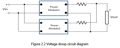
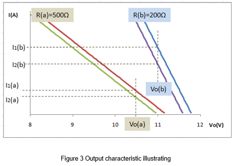
The voltage droop method is connecting an external resistor at the output of the power converter to let the output voltage reduce, as the load current increases. This method has no signal connection between the power converters and is not affected by each other. It is an open loop current sharing method.
The following figure 3 simulates the two parallel systems of a and b, with external resistors of 500 and 200 ohms respectively. It can be seen that the output current difference between the two power converters in group a is smaller than group b. When the external output resistance increases, the output current difference between the two modules can be reduced to achieve the average current.
The voltage droop method can achieve current sharing in the simple way, and each power module is independent, without additional control circuit. However, power modules with larger currents will consume more power because the resistors result in lower output efficiency, and it is difficult to perform current sharing between power converters of different powers. This is the biggest disadvantage of the voltage droop method.
Active current sharing method
The active current sharing method is to connect to each power module through a current sharing bus, collect the current signal from all power modules as a reference signal. The power modules adjust the output voltage through the result of output current compare with the bus signal, and make the output current tend to be the same. There are three ways to generate the reference signal
- Average Current Method
All converters provide the signals of their output currents, and this signal is used to be the reference signal of each module. For example, a power converter with a lower output current will compare the signal from the current sharing bus and increase the output voltage so that its output current is made approximately equal to the average the output current. The advantage is that there are fewer signal lines and strong anti-noise ability. However, when certain problems are encountered, the entire system cannot operate. For example, when a converter runs into a current limit, the output voltage will be adjusted to 0V. So the current signal of sharing bus will decrease, other power modules will continuously reduce their output current, causing the whole current sharing system to lose its function.
- Directed Master-Slave Current-Sharing
Specify a master power modules, and others are slave power modules. That is, the current signal of the master power module is used as a reference signal, and other power modules follow this signal to adjust their own voltage to achieve the effect of current balance. The disadvantage is that when the master power supply is damaged, the entire system loses the reference signal and becomes directly connected in parallel. The system will lose the effect of active current sharing.
- Automatic Master-Slave Current-Sharing
This system can automatically select the master power module which has the maximum current by connecting a diode. The master module provides the signal to the current sharing bus, and other slave modules will get the signal as reference and adjust output voltage. Because the master power module can be replaced. So if one of the power modules is damaged, the whole parallel system will not be affected. It would have the better reliability.
Current sharing controller
There are many active current sharing ICs on the market that can be used as external controllers. Generally, each power module needs to be connected with an external controller, and then each controller receives and processes the current signal from all power modules. The controller provides a signal to each power module and adjusts accordingly control signals to correct the imbalance of output current. Although this method can achieve higher current sharing accuracy, it usually has more complicated circuit design and relatively high cost.
ORing diode
When two power converters are connected in parallel, the output voltages of the two power converters will not be exactly the same due to component tolerance and trace, etc. Therefore, a power supply with the higher output voltage may cause the countercurrent to other power converters, and the damage might be occurred. An ORing diode is placed in output path of converter, so that the current of each power module can only flow to the load end. Another advantage is that it can support the implementation of ‘N+1’ redundant design. The N+1 architecture adds at least one additional power module. When one of the power converters is failed, the diode can protect the other power modules from being affected and maintain the output function of the system.
Application
This article chooses to use an external controller to realize the parallel and current sharing of two independent power converters. Selected two 40W DC power converters for parallel and TI's (Texas Instruments) current sharing controller UCC39002. The current sharing circuit should control the accuracy of output current sharing within 1%.
IC function
UCC39002 is set to automatic master-slave method. The detection resistor and internal amplifier determine the master converter with the larger output current, and the others are the slave converters. The current difference between the master and slave converter will generate an error signal. The sense pin and the external resistance promote the increase the output voltage, thus the output current of slave converter will increase to perform current sharing. Figure 5 shows the IC function block diagram.
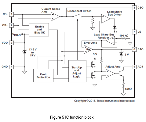
- Current sense amplifier
There is a detection resistor (Rshunt) between the CS+ and CS-, and the current sense amplifier amplifies the small voltage drop across the detection resistor, and the signal is used to the back-end circuit.
- Load share bus driver
Load share bus driver receives the signal from the current sense amplifier. When this signal is the highest among all power modules, it will generate a forward bias to the diode and become the master power supply. For other power supplies, the VCSO and VLS signals are separated due to the reverse bias of the diode. That allows the error amplifier to compare its respective module’s output current to the master module’s output current and make the necessary corrections to achieve a balanced current distribution.
- Load share bus receiver
Load share bus receiver can monitor the load share bus voltage, and then send the signal of the main power supply to the error amplifier.
- Error amplifier
The two ends of the error amplifier come from the current signal of the master module and own current sense amplifier, and compares two signals. If the current signal of the master power is higher than the module's own output current, an error signal will be generated in the compensation component between EAO and GND. The error signal is used by the adjust amplifier to make the necessary output voltage adjustments to ensure equal output currents among the parallel operated power supplies. In case the UCC39002 assumes the master load share controller in the system, the measured current signal on VCSO and VLS is approximately equal.
- Adjust amplifier
The error signal of the adjustment amplifier is used to drive the transistor. The current flows through the adjust resistor RADJ and changes the output voltage of the module. At the master module VEAO is 0 V, so the adjust current must be zero. This ensures that the output voltage of the master module has not changed.
Experiment
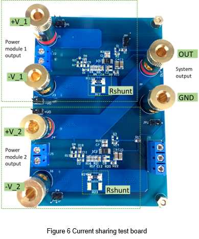
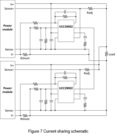
Figure 6 shows the actual current sharing test board, which contains two sets of control circuits. In addition, LS terminals are reserved to meet the multiple parallel modules.
Experimental condition
The following table shows the specifications of the DC/DC power converter for this experiment.
| DC to DC Converter | 40W |
| Input voltage | 9-60Vdc, Nom.24Vdc |
| Output voltage | 12Vdc |
| Output current (full load) | 3.33A |
| Efficiency (typ.) | 91% |
Experimental parameter setting
The external components required by the IC should be determined according to the specifications of power module. The following is the design description of each parameter
Current sense resistor
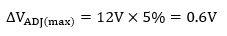
Since the current detection resistor is connected in the current loop of the power converter. It must be ensured that when the output current is maximum, and the voltage drop across the resistor is much less than the maximum output voltage adjustment range of the module. The maximum output voltage adjustment range of the converter is set to 5%.
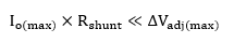
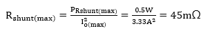
The detection resistor should be considered the power consumption and the rated resistance value. Thus the maximum power consumption is limited to 0.5W, and the maximum allowable value of the detection resistor can be calculated.
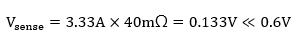
Choose 40mΩ as the detection resistance, and confirm that VRSENSE is much less than ΔVADJ.
The CSA gain
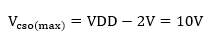
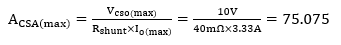
The gain of the current sense amplifier is adjusted by the external components of CS- and CSO and, to avoid saturating the internal amplifier, VCSO(max) is limited to:
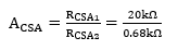
The maximum gain of the current sense amplifier is
The maximum gain of the current sense amplifier is selected as 30, and it is set by RCAS1 and RCSA2
In order to filter out the noise, the capacitance value of the CCSA can be calculated by the following formula
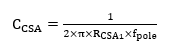
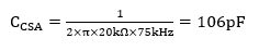
CCSA is equal to the actual capacitor value selected for this pole, 100pF.
Adjust resistor
The Sense+ of the power converter is connected to the ADJ pin of the controller, and a resistor RADJ is placed between the Sense+ and load. The load share controller’s adjust amplifier will sink current through this resistor proportional to the error amplifier output voltage, so it can change the output voltage of the power converter through the voltage drop of RADJ. When the output voltage of the power converter increases, its output current also increases relatively until the error amplifier output turns off the adjust amplifier.
The selection of resistance must keep the internal transistor from saturating, so the voltage on the ADJ pin must be greater than or equal to the error amplifier output voltage, VEAO, by at least 1 V.
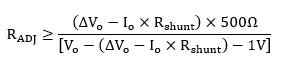
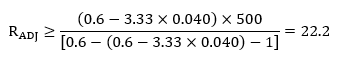
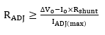
Also needed for consideration is the maximum sink current for the ADJ pin, which is 6 mA as determined by the internal 500-Ω emitter resistor and 3-V clamp. Assuming that the maximum voltage drop of RADJ is not greater than the maximum output voltage adjustment range of the power module.
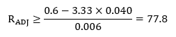
In order to meet the above two conditions, 100Ω is chosen as the adjustment resistor.
Application circuit
Result
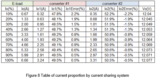
Using two DC power converters of the same specification confirm the current sharing controller. Given two converters with the same input source of 24Vdc, and the power converters will stably output 12Vdc. The data will be recorded with every 10% increase in the load current, include the output voltage, output current, and total output voltage of each power converters. And calculate the respective current distribution ratio and error, as shown in Figure 8.
In Figure 8, it can be observed that the error of the output current within 0.5~2.2%. When the output load is higher than 50% of the full load, the error is less than 1%. And the output voltage (VO) of the parallel system can be controlled within 1% of the converter's accuracy specification. Therefore, the power converter is connected to the current-sharing control circuit, the output voltage accuracy and output efficiency can meet the specifications of the power converter.
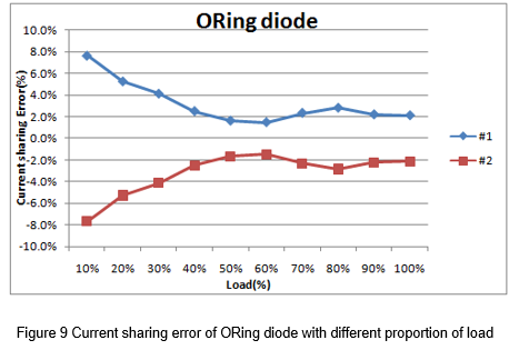
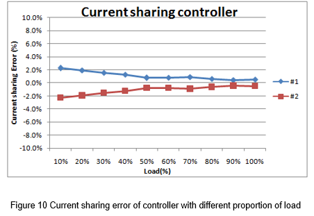
Make a graph of the current sharing error and the load ratio. As shown in Figure 9, there is not used current sharing controller, and only a diode is added to the output terminals of the two power converters. Figure 10 shows the converter with current-sharing control circuits. It can be clearly seen that the current sharing accuracy of Figure 10 is higher. And when the load current is larger, the current sharing effect is better.
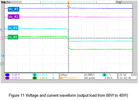
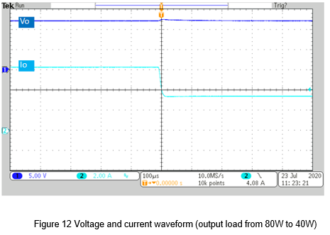
In general applications, dynamic load conditions must be considered. When the load current changes instantaneously, the output current and voltage should not be affected. Figure 11 shows the output voltage and output current of the two power converters, and captured the waveform that the output drops from 80W to 40W. Figure 12 shows the total output voltage and output current of the system. It can be observed from the figure below that the output voltage and current of the system remain stable when the load changes.
Notice
To achieve better accuracy of the current sharing system, it recommended completing the following items
- For converters connected in parallel, the input source should be provided by the same power supply to ensure that the input voltage of each converter is the same, and the timing difference can also be minimized.
- The current path through the wire and PCB copper will cause current loss. Therefore, the length of the wiring path needs special attention. The design should base on the principle of path symmetrical in each group of current sharing circuits.
Conclusion
This article uses the existing DC power converter to design an external current sharing circuit to perform a parallel connection and increase the overall output power. The actual experimental results can confirm the feasibility of a parallel connection. When the output load is higher than 50% of the full load, the current sharing error is less than 1%. When the output is a full load, the current sharing error can be reduced to 0.5%. And the overall output voltage and current can still remain stable under dynamic load conditions. Therefore, the feasibility of this parallel system can be confirmed.
CTC is a professional service provider for high-end power supply modules (AC to DC Converter and DC to DC Converter) for critical applications worldwide since 30 years. Our core competence is to design and deliver products with leading technologies, competitive pricing, extremely flexible lead-time, global technical service and high-quality manufacturing (Made In Taiwan).
CTC is the only corporation certificated with ISO-9001, IATF-16949, ISO22613(IRIS), and ESD/ANSI-2020. We can 100% ensure not only the product, but also our workflow and service to match quality management system for every high-end application from the very beginning. From design to manufacturing and technical support, every single detail is operated under highest standard.