

You are here
Back to topQuiescent, Shutdown and Leakage Current Guide
Driven by the industry trend toward higher power density and greater energy efficiency, accurate understanding of nanoamp-level current consumption is critical for evaluating module reliability and efficiency. This paper systematically explains the fundamental differences between quiescent current, shutdown current, and leakage current, and analyzes how light-load/heavy-load transitions, component abnormalities, and environmental factors affect these parameters. It also summarizes practical design and component selection considerations. Proper differentiation of these current specifications helps prevent misinterpretation and improves the stability and reliability of power modules under low-power and long-term operating conditions.
Introduction
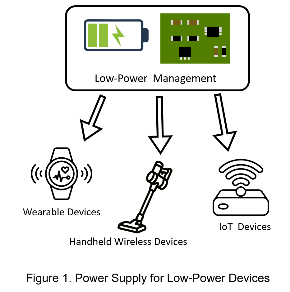
Global demand for wearable devices, IoT sensors, and active implantable medical devices is experiencing explosive growth. However, most of these devices rely on limited battery energy. As shown in Figure 1, the foremost challenge in contemporary power management design is maximizing battery life by minimizing power consumption while simultaneously enhancing system performance.
In standard definitions, power converter datasheets typically specify test conditions for standby, quiescent, and leakage currents. Some of these parameters involve the device state after the Enable (EN) pin is deactivated, or the power consumption under various load conditions, which can easily confuse users. Furthermore, the measurement methodologies and setups for quiescent and shutdown currents significantly impact how designers evaluate these performance indicators.
Overall, quiescent and shutdown currents are electrical metrics that designers actively aim to minimize. In contrast, leakage current primarily stems from isolation structures and parasitic capacitance effects, requiring mitigation through robust insulation design, material selection, creepage/clearance planning, and manufacturing quality control. The following sections provide an in-depth analysis to clearly distinguish the characteristics and interactions of these three currents, followed by a comparison of their measurement methodologies.
Three Current Definitions: Distinctions and Practical Considerations
Definition and Distinctions of Quiescent, Shutdown, and Leakage Current
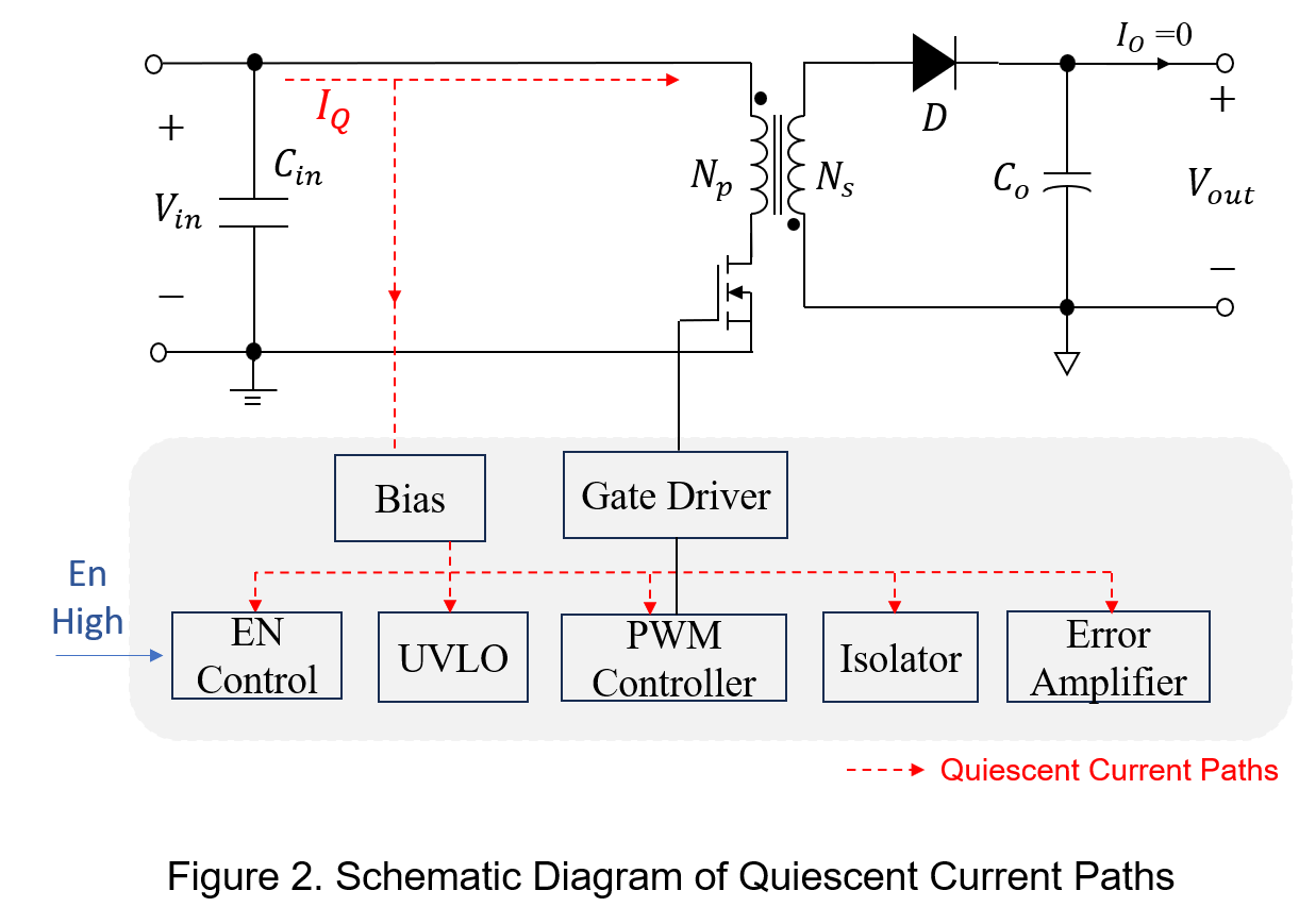
Quiescent current  IQ refers to the input current consumed by a power converter when the Enable (EN) pin is active (logic high) and the converter is in the ON state, but with no load connected to the output. In this state, the converter operates normally to maintain its voltage regulation function, as illustrated in Figure 2.
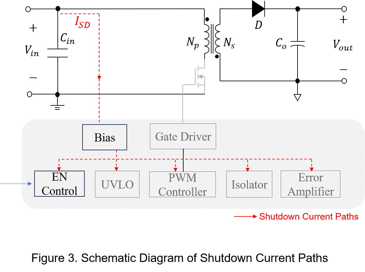
Shutdown current ISD significantly affects the long-term shelf life of a product. When the EN pin is pulled low, the power converter enters Shutdown Mode, where a minimal current is still required to sustain internal control logic, biasing, and protection circuits. If shutdown current is excessively high, it will continuously drain the battery even when the product is powered off but connected to the source. This can lead to severe over-discharge, battery depletion, or a complete failure to power on.
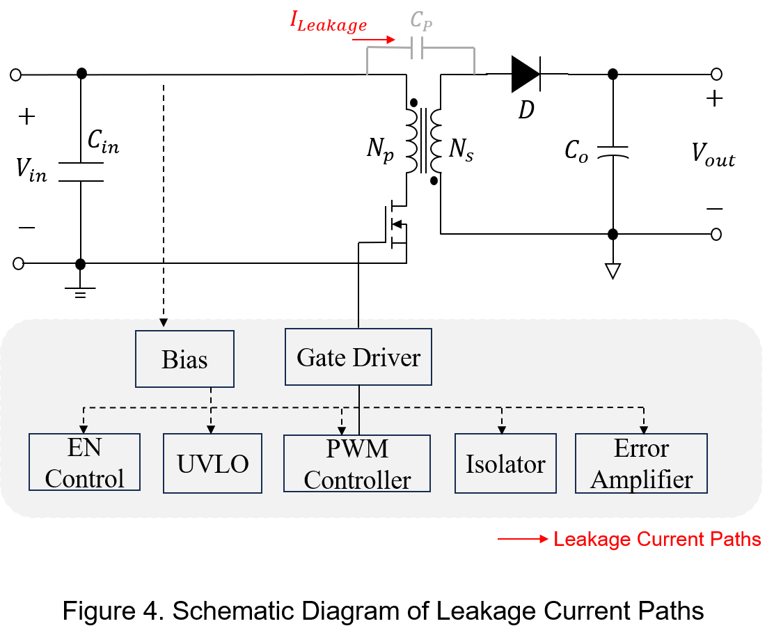
Leakage current refers to the intrinsic conduction current through insulating materials, combined with common-mode paths created by transformer winding parasitic capacitances. Specifically, between the primary and secondary sides of a transformer, compromised insulation layers or excessive surface potential gradients can create additional leakage risks across interface paths. These unintended paths are often exacerbated by flux residues or PCB moisture absorption, accelerating battery drain under extreme operating conditions.
Measurement of Quiescent and Shutdown Current
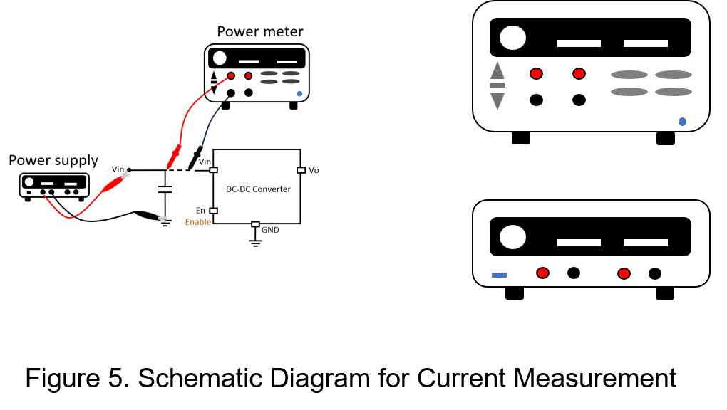
When measuring quiescent current, the output terminal should be maintained under a no-load or specified light-load condition, while the EN pin is set to logic high to maintain the power converter in an enabled state. In this mode, the internal bias, control, oscillator, and driver circuits remain fully operational. As shown in Figure 5, an ammeter or power meter should be connected in series with the input terminal, and the measured input current serves as the reference value for the quiescent current.
When measuring shutdown current, the EN pin must be pulled to a logic low to transition the converter into shutdown mode. In this state, the output voltage typically drops to 0 V, while the PWM, oscillator, and driver circuits are disabled, leaving only the essential bias, protection, and wake-up circuits functional. the minimal current measured from the input terminal under these conditions represents the reference value for the shutdown current.
Analysis of Quiescent, Shutdown, and Leakage Current
Although quiescent, shutdown, and leakage currents are all categorized under low-power specifications, their underlying factors and design considerations differ significantly.
Quiescent current primarily occurs when the power converter is enabled but the output is under a no-load or light-load condition. In this state, internal circuits—such as the biasing networks, PWM controller, oscillator, error amplifier, control logic, and gate drivers—must remain fully operational, thereby consuming a constant baseline current. When the system transitions from a heavy load to a light load, although the output power drops significantly, this internal circuit consumption persists, making the impact of quiescent current on overall efficiency far more pronounced. For example, when an IoT sensor enters standby mode, the output current drops substantially, making quiescent current one of the dominant sources of power loss.
Factors affecting quiescent current include the control IC architecture, operating mode, switching frequency, gate driver power consumption, and the condition of external components. For example, gate driver abnormalities or degraded coupling capacitors may increase quiescent current. In addition, high-temperature environments may worsen semiconductor leakage, further increasing the quiescent current.
Shutdown current occurs when the EN pin is pulled low, placing the converter into Shutdown Mode. In this state, the PWM controller, oscillator, and gate drive circuitry are mostly disabled, leaving only the essential biasing, protection, and wake-up circuitry active; consequently, shutdown current is typically orders of magnitude lower than quiescent current.
Factors affecting shutdown current include EN pin bias conditions, UVLO circuitry, and startup circuit leakage. In addition, PCB flux residue or moisture absorption may create additional leakage paths. For battery-powered systems, even extremely small shutdown currents can lead to severe battery capacity degradation over long-term storage.
Although leakage current is typically negligible in a well-designed system, directly impacts the long-term safety, efficiency, and reliability of the power system. Its primary driving factors include:
- Transient Voltage Stress: High DC voltage bias or repetitive switching spikes increase the electric field intensity, accelerating insulation material degradation and partial discharge phenomena.
- Material and Manufacturing Quality: The volume resistivity and dielectric loss of insulating materials directly dictate the leakage current, while microscopic air gaps introduced during manufacturing can create potential leakage channels.
- Aging Effects: Under long-term operation, insulating materials gradually degrade due to thermal stress and mechanical vibration, causing leakage current to increase over time.
Conclusion
In low-power supply design, quiescent, shutdown and leakage current all affect system efficiency, reliability, and battery life, but their origins and impacts are different. Quiescent current mainly affects standby and light-load efficiency, while shutdown current is closely related to battery drain during long-term storage. Leakage current not only affects efficiency, but also directly influences isolation safety and long-term reliability.
CTC is service provider for high-end power modules (DC to DC Converter and AC to DC Converter) for critical applications worldwide since 1987. We aim to be business generator and a virtual business unit. CTC is your own team with 35 years of experience for a strong business program from market research, product definition & development, supply chain management and total technical services.
CTC is the only corporation certificated with ISO-9001, IATF-16949, ISO22613(IRIS), and ESD/ANSI-2020. We can 100% ensure not only the product, but also our workflow and service to match quality management system for every high-end application from the very beginning. From design to manufacturing and technical support, every single detail is operated under highest standard.