

You are here
Back to topPower Converter Control Architecture
The electrical performance of a power converter is fundamentally determined by its feedback control architecture. Control loop design affects not only steady-state regulation accuracy, but also dynamic response, loop stability, and transient recovery performance. Even when based on the same control theory, differences in power-stage configuration and compensation design can lead to variations in overall performance.
This article focuses on Pulse-Width Modulation (PWM) control architectures and provides a systematic overview of Voltage Mode Control (VMC) and Current Mode Control (CMC). The operating principles of each method are first examined, followed by a comparative analysis of loop compensation complexity, load transient response, stability margin, and overall dynamic performance.
Introduction
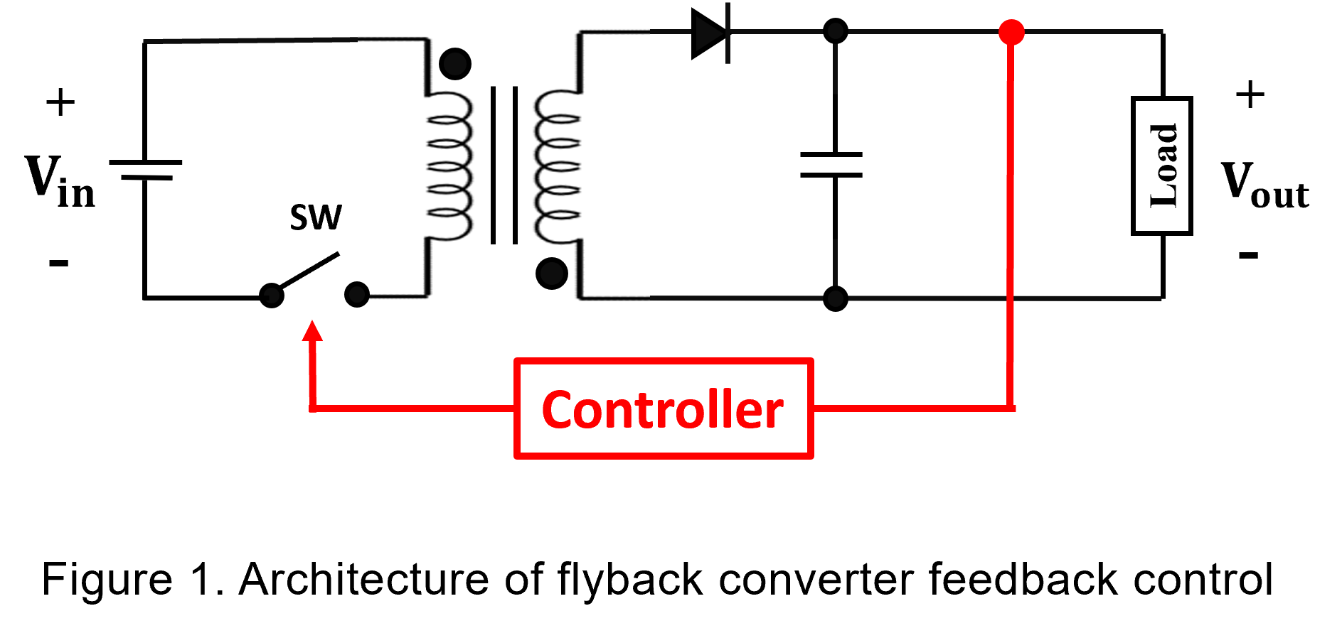
Feedback compensation is an essential design mechanism in power converters, ensuring stable output voltage across varying input and load conditions. The control architecture directly influences regulation accuracy and dynamic response, as shown in Figure 1. The most common PWM control approaches are Voltage Mode Control (VMC) and Current Mode Control (CMC).
In voltage-mode control, the output voltage of the power converter is sampled through a feedback circuit and used as the feedback signal. The error amplifier compares the sensed output voltage with a reference signal generated from a sawtooth waveform to produce an error signal. This error signal is then used to adjust the duty cycle of the PWM signal, compensating for changes in input voltage or load conditions and thereby stabilizing the converter’s output voltage.
However, when using voltage-mode control converters, certain limitations may arise. For example, the system may respond relatively slowly to sudden load changes, and the loop gain may vary with different input voltages. Current-mode control can mitigate these issues. By incorporating inductor current as part of the control signal, current-mode control enables faster response to load variations and provides more stable loop gain characteristics. The following sections introduce these two control methods in detail and provide a comparative analysis.
Basic Principles of Control Theory
In control theory, transfer functions and loop analysis are commonly used to evaluate system stability and response speed. For power converters operating near their nominal conditions, the system can typically be approximated as linear for analytical purposes.
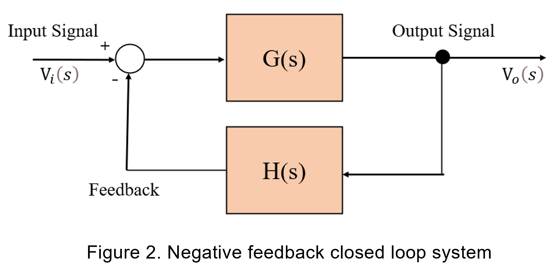
Control systems can be categorized as either open-loop or closed-loop. In an open-loop system, the output does not influence the input, meaning that errors cannot be corrected automatically. In contrast, closed-loop systems feed the output signal back to the controller (as shown in Figure 2), enabling the system to self-adjust and maintain stable operation.
Control systems can also be classified based on the phase relationship of the feedback signal. If the feedback signal has an opposite phase relative to the system signal, it is referred to as negative feedback. Conversely, if the feedback signal has the same phase as the system signal, it is referred to as positive feedback.
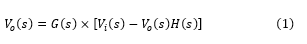
The following is the transfer function of the closed loop system:
Simplified as follows:
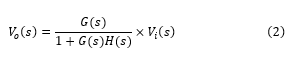
According to Equation (2), the closed-loop transfer function is less affected by variations in the plant G(s), effectively reducing the sensitivity of the control system to plant variations and minimizing the impact of input disturbances. In power converters, closed-loop control modes mainly include voltage-mode control and current-mode control, which employ different feedback signal sampling methods. Both approaches regulate the PWM signal to adjust the duty cycle, thereby controlling and stabilizing the output voltage.
PWM duty cycle
The duty cycle in PWM control refers to the percentage of time that the switching element remains in the ON state within a single switching cycle. Power converters regulate the output voltage by adjusting this ON-time ratio of the switching element.
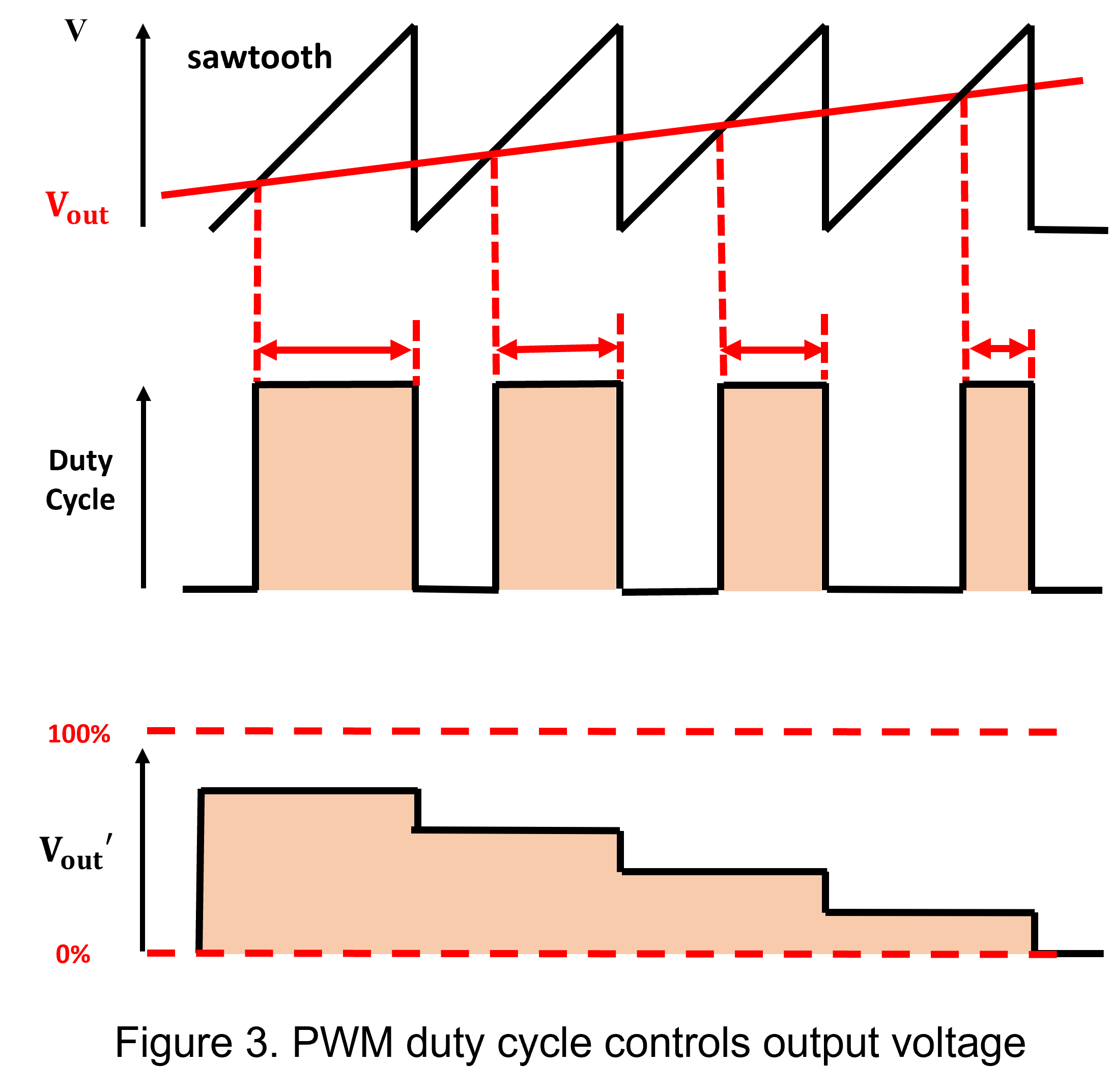
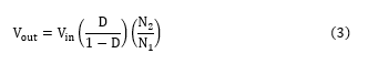
The following is the transfer function of ideal flyback converter, where the relationship between the output voltage and the input voltage is given by equation (3):
If the actual output voltage value (Vout) falls below the target voltage, according to equation (3), the switching element is controlled to increase the duty cycle, resulting in a rise in the output voltage (Vout'). Conversely, when the output voltage exceeds the design voltage (Vout), feedback control can decrease duty cycle, and then causing the output voltage (Vout') to decrease.
Voltage Control Mode
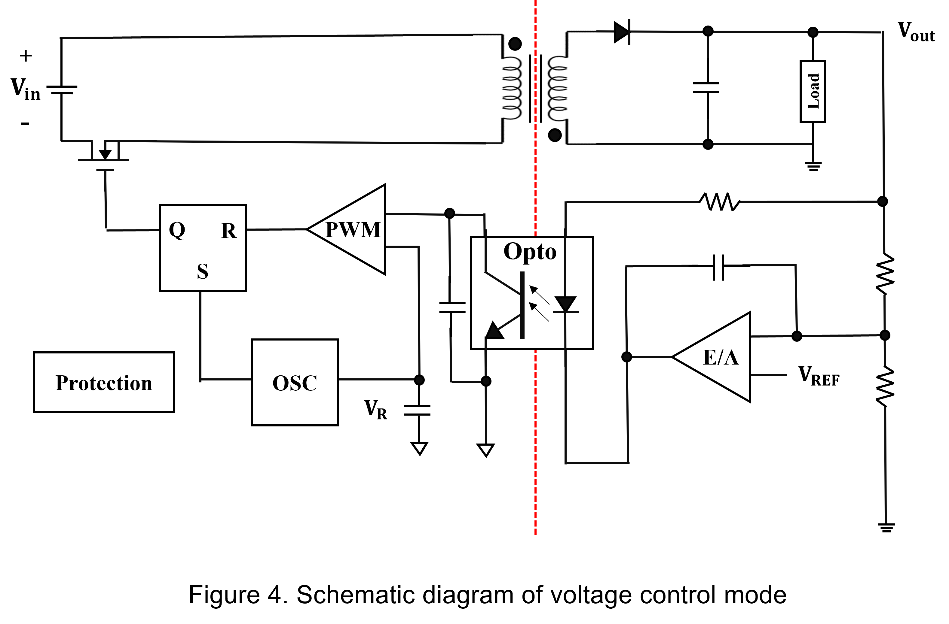
Voltage Mode Control (VMC) operates by sampling the output voltage through a feedback network and comparing it with a reference voltage at the error amplifier (E/A). The resulting error signal is then compared with a fixed-frequency sawtooth waveform generated by the oscillator (OSC) within a PWM comparator. This comparison determines the switching duty cycle, thereby regulating the output voltage, as illustrated in Figure 4.
(1) Advantages and Disadvantages
VMC is a single-loop control architecture with straightforward implementation and well-established compensation techniques. It generally provides good noise immunity against switching disturbances.
However, its dynamic performance is constrained by the double pole introduced by the LC output filter, which results in a slower transient response during rapid load changes. Consequently, a more sophisticated compensation network is often required to maintain an adequate phase margin.
In addition, the loop gain varies with input voltage and operating conditions, which may lead to variations in regulation accuracy and dynamic performance across a wide input voltage range.
(2) Design Considerations
In PCB implementation, feedback trace routing significantly affects system performance. Excessive trace impedance or proximity to high dv/dt switching nodes can introduce noise coupling, degrading regulation accuracy and loop stability.
Recommended layout practices include:
- Minimizing the feedback trace length and keeping it away from switching nodes
- Increasing trace width to reduce parasitic impedance
- Employing electrical isolation or differential sensing where necessary
These measures help improve noise immunity and enhance output voltage accuracy.
Current Control Mode
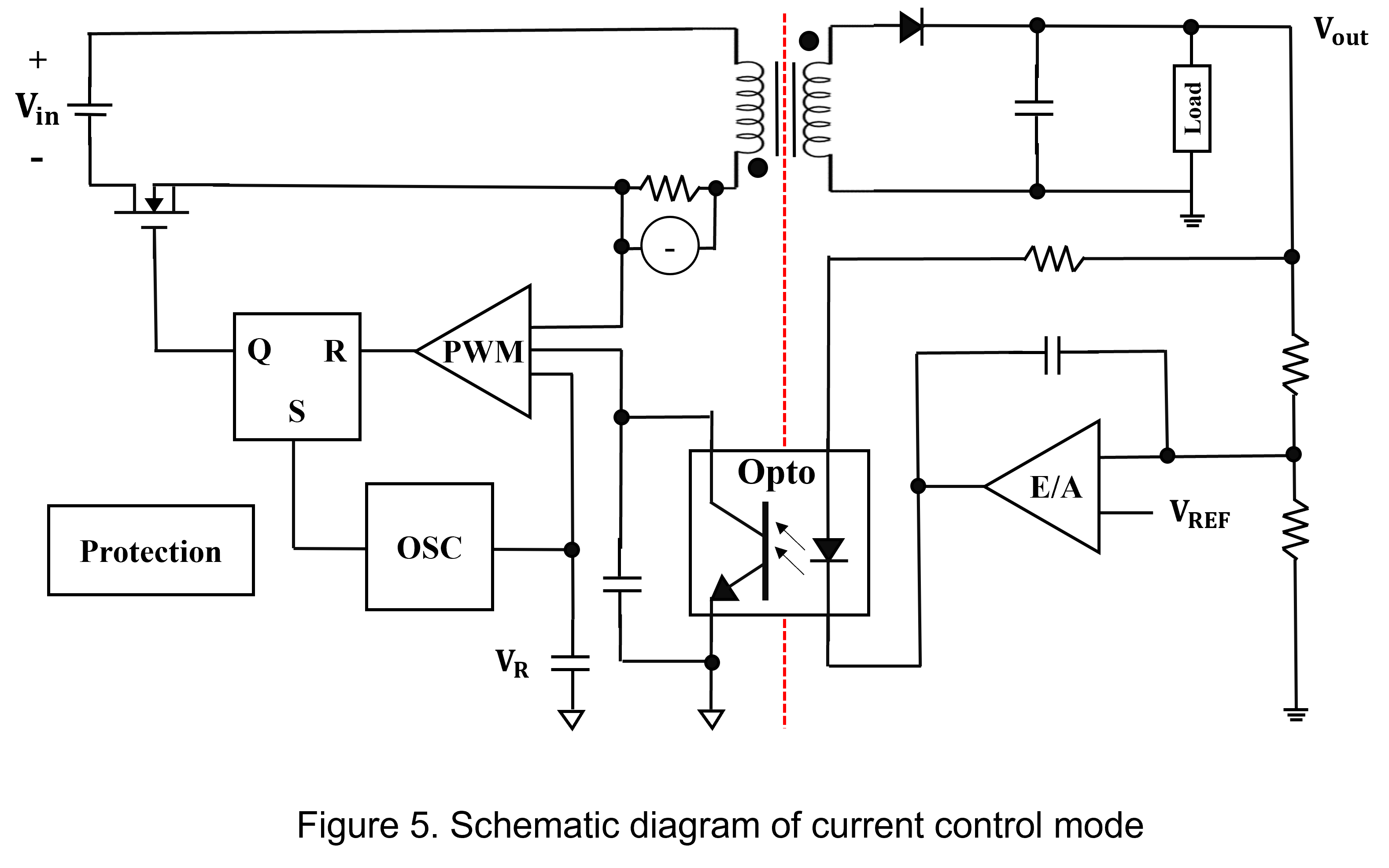
A current-mode control system includes both a voltage feedback path and a current feedback path. The current feedback path senses the primary-side current of the transformer, while the voltage feedback path detects the output voltage and compares it with a reference voltage to generate an error signal.
This error signal is processed by the compensator to determine the required control action. The current feedback signal is then combined with the compensated voltage error signal to generate the PWM control pulse, as illustrated in Figure 5.
(1) Advantages and Disadvantages
Current Mode Control (CMC) employs a dual-loop architecture consisting of an outer voltage loop and an inner current loop. Although it is structurally more complex than Voltage Mode Control (VMC), the compensation design is simplified because the inner current loop effectively reduces the power-stage order to a single dominant pole, improving phase margin and overall loop stability.
CMC provides superior transient response and maintains more consistent loop gain across wide input voltage and load variations. However, the use of current-sensing components (such as sense resistors or current transformers) introduces additional conduction losses, which may reduce conversion efficiency. Furthermore, when operating in Continuous Conduction Mode (CCM) with duty cycles exceeding 50%, the system may exhibit subharmonic oscillation.
(2) Design Considerations
In current-mode control architectures, system stability is closely related to the primary-side current waveform. During CCM operation with duty cycles above 50%, insufficient slope compensation may lead to subharmonic oscillation.
Recommended design practices include:
- Implementing appropriate slope compensation at higher duty cycles
- Optimizing current-sense routing to minimize parasitic effects
These measures help ensure stable and reliable operation across a wide operating range.
Which Loop Control Should Be Chosen?
Voltage Mode Control and Current Mode Control are two commonly used PWM control methods. As electronic systems demand higher power density, efficiency, and tighter regulation, selecting the appropriate control architecture has become increasingly important.
In many medium- to high-power applications, Current Mode Control has become the preferred approach due to its superior transient performance and improved stability characteristics. However, with advances in highly integrated control ICs, many limitations traditionally associated with Voltage Mode Control can now be mitigated through improved compensation techniques and built-in control features.
Therefore, designers can select the most appropriate control scheme based on application requirements and system specifications. The following table compares the performance characteristics of these two control architectures.
|
Voltage control mode |
Current control mode |
|
| Voltage stabilization effect | Poor | Good |
| Load response speed | Slow | Fast |
| Compensation circuit design | Complex | Simple |
| Noise tolerance | High | Low |
Summary
In summary, selecting a power converter control architecture involves balancing dynamic performance and design complexity.
If the primary design objective is to achieve maximum voltage stability and rapid response to large load transients, Current Mode Control offers significant advantages. On the other hand, if the system is sensitive to noise interference or requires a simpler circuit implementation, Voltage Mode Control remains a reliable and effective solution.
Designers are encouraged to evaluate these control architectures based on specific application requirements to ensure that the power module operates with optimal performance.
CTC is service provider for high-end power modules (DC to DC Converter and AC to DC Converter) for critical applications worldwide since 1987. We aim to be business generator and a virtual business unit. CTC is your own team with 35 years of experience for a strong business program from market research, product definition & development, supply chain management and total technical services.
CTC is the only corporation certificated with ISO-9001, IATF-16949, ISO22613(IRIS), and ESD/ANSI-2020. We can 100% ensure not only the product, but also our workflow and service to match quality management system for every high-end application from the very beginning. From design to manufacturing and technical support, every single detail is operated under highest standard.