

You are here
Back to topTest Environments and Regulatory Requirements for ESD, EFT, and Surge
Electromagnetic Susceptibility (EMS) is a key indicator used to evaluate the resistance of electrical equipment and components against external electromagnetic interference.
As electronic devices become increasingly prevalent in modern life and their usage density continues to rise, the importance of EMS has also gained growing attention.
Among the various EMS test items, Electrostatic Discharge (ESD), Electrical Fast Transient (EFT), and Surge testing are the three most common tests specified for power converters.
These tests are primarily designed to verify a device’s tolerance to sudden high-voltage and high-current disturbances, which are closely related to product reliability and operational safety.
This article explores the sources and formation mechanisms of ESD, EFT, and Surge interferences; explains the purpose of each test; and, based on the IEC 61000 series of standards, introduces the required test equipment setups, testing conditions, and the specified test levels for these three types of EMS tests.
Introduction
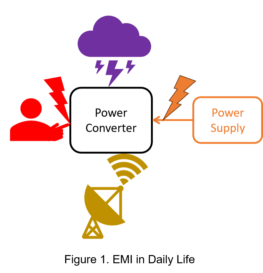
In real-world applications, power converters are exposed to a wide range of electromagnetic interference (EMI) from various sources, as illustrated in Figure 1.
These sources include high currents induced by lightning strikes, electrostatic discharges (ESD) caused by human contact, radiated noise emitted by wireless communication systems, and conducted noise and fast transient disturbances generated during power switching or connection events.
Given the diversity of these interference sources, conducting EMS testing is especially critical.
The primary objective of such testing is to enhance the converter's immunity to external electromagnetic disturbances, ensuring stable and reliable operation under all working conditions.
IEC 61000 is a series of test standards developed by the International Electrotechnical Commission (IEC) specifically for electromagnetic compatibility (EMC).
The sub-standards within IEC 61000 define the procedures, methodologies, test equipment setups, and evaluation criteria for each type of test.
Due to its broad applicability and rigorous standardization, IEC 61000 has become a key reference for many regional and national standards, including those of the European Union.
Within the scope of electromagnetic susceptibility (EMS) testing, the standard addresses several common forms of electromagnetic interference (EMI), including:
- Electrostatic Discharge (ESD)
- Electrical Fast Transient (EFT)
- Surge
- Conducted Immunity (CI)
- Radiated Immunity (RI)
- Power Frequency Magnetic Field (PMF)
- Voltage Dips
- Ring Wave
- Harmonics and Interharmonics
This article will focus on three critical EMS tests: ESD, EFT, and Surge.
Based on the relevant sub-standards within the IEC 61000 series, we will individually examine the purpose of each test, required test equipment configurations, and the corresponding test level requirements.
Test Environment and Regulatory
(1) ESD
Electrostatic Discharge (ESD) is a phenomenon that occurs when an imbalance of electrical charges on the surface of objects leads to a discharge of electricity, triggered by a sufficient potential difference. When two objects come into close proximity or contact, static charges can be rapidly released, generating a high-current pulse that may damage sensitive electronic components.
The applicable standard for ESD is IEC 61000-4-2, which provides detailed specifications on test methods, waveform parameters, and test levels for ESD evaluation. Regarding the current waveform characteristics (see Figure 2):
Rise time (Tᵣ): The rise time of the first peak current, measured between 10% and 90% of its amplitude, ranges from 0.7 to 1 ns.
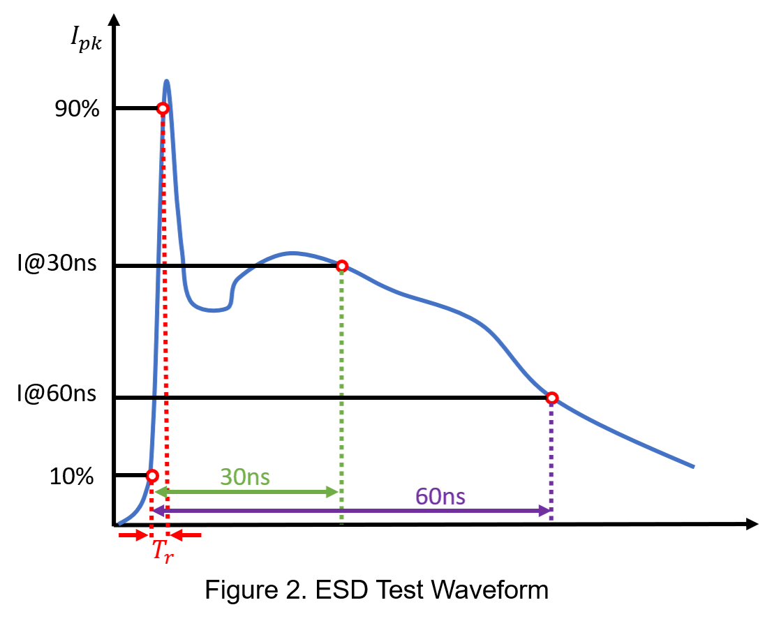
The ESD test is conducted using two methods: Contact Discharge (CD) and Air Discharge (AD). Each method specifies four test levels, which define parameters such as the test voltage, the first and second peak currents, and the current values at 30 ns and 60 ns.
| Level | Test Voltage (kV) | First Peak Current (A) | Second Peak Current (A) | Current @30ns (A) | Current @60ns (A) | |
| CD | AD | |||||
| 1 | 1 | 2 | 7.5 | 4.5 | 4 | 2 |
| 2 | 2 | 4 | 15 | 9 | 8 | 4 |
| 3 | - | 6 | 22.5 | 13.5 | 12 | 6 |
| 4 | 3 | 8 | 30 | 18 | 16 | 8 |
| - | 4 | 15 | 56.3 | 33.8 | 30 | 15 |
The ESD waveform is generated using an electrostatic discharge simulator and delivered through an ESD gun. The test waveform is formed at the tip of the ESD gun, which is designed to replicate real-world discharge events. The discharge model of the electrostatic discharge simulator is illustrated in the figure below:

The voltage source first charges the storage capacitor Cₛ through the charging resistor R꜀. Once the switch is triggered, the storage capacitor discharges through the discharge resistor Rᴅ into the Device Under Test (DUT). The typical values of these three components are as follows:
- Charging resistor
 RC : 50M~100MΩ
 - Storage capacitor CS
 : 150pF
- Discharge resistor RD
 : 330Ω
(2) EFT
Electrical Fast Transients (EFT) primarily originate from operations such as power switching, relay contact bounce, and the interruption of inductive loads. These events generate high-frequency, low-energy bursts of pulses that can couple into electronic equipment through power lines, signal lines, or the grounding system. Such interference may cause malfunctions or even physical damage to the system.
The corresponding international standard is IEC 61000-4-4, which specifies the immunity requirements and test procedures related to EFT. This includes definitions of the test waveform, equipment setup, and classification of test levels. The purpose of the standard is to establish a consistent basis for evaluating a device’s immunity to EFT.
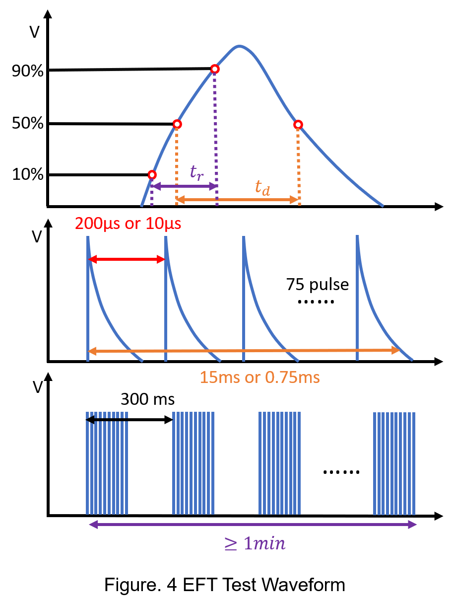
The EFT test waveform consists of two components: individual pulses and bursts of pulses. The standardized waveform is defined as follows:
[1] Individual pulse:
- Rising time(tr ): 5 ns (measured from 10% to 90% of the peak value)
- Duration(td): 50 ns (measured from the 50% point on the rising edge to the 50% point on the falling edge)
- Pulse frequency: configurable to either 5 kHz (200 μs period) or 100 kHz (10 μs period)
[2] Burst of pulses:
- Each pulse burst consists of 75 pulses, resulting in a burst duration of 15 ms at 5 kHz (low frequency) or 0.75 ms at 100 kHz (high frequency)
Repetition period of each burst 300 ms, total test duration: Minimum of 1 minute
EFT test levels are classified into four categories based on the coupling method, either through power lines or signal lines. The performance criteria are defined as follows (only Criteria A and B are considered a pass):
- Criteria A: Normal operation — the equipment continues to function as intended.
- Criteria B: Temporary loss of function or performance, which recovers automatically.
- Criteria C: Temporary loss of function or performance, recovery requires operator intervention (e.g., manual restart).
- Criteria D: Permanent loss of function or damage to the equipment.
| Level | Power Port (kV) | Signal Port (kV) |
| 1 | 0.5 | 0.25 |
| 2 | 1 | 0.5 |
| 3 | 2 | 1 |
| 4 | 4 | 2 |
The pulses are generated by an EFT burst generator, which emits transient pulse bursts. The model of the pulse generator is shown in Figure 5:

RC is the charging resistor, CC is the storage capacitor, RS shapes the pulse duration,  RM is the impedance matching resistor, and CD
 is the isolation capacitor. The output impedance
  Zout is 50 ohms.
The switch in the circuit controls the pulse repetition frequency, thereby determining the pulse frequency for the EFT test.
(3) Surge
Surge disturbances primarily originate from lightning strikes or power switching operations, generating high-energy transient voltages and currents that can couple into electronic systems through power lines, signal lines, or grounding paths. Because of their high energy, insufficient protection may cause severe damage to power converters or other critical components. Therefore, it is essential to incorporate surge suppression circuits or overvoltage/overcurrent protection mechanisms during system design.
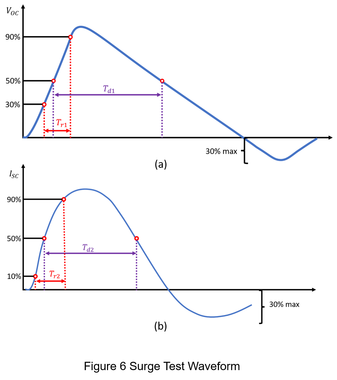
The applicable international standard is IEC 61000-4-5, which defines the surge test waveform, test levels, and testing procedures. The surge test waveforms are categorized into two types:
[1] Open-circuit voltage waveform (Figure 6(a)):
- Front timeTr1 : 1.2 μs (defined as 1.67 times the 30% to 90% rise time)
- Time to half-valueTd1 : 50 μs (measured from the 50% point on the rising edge to the 50% point on the falling edge)
[2] Short-circuit current waveform (Figure 6(b)):
- Front time Tr2 : 8 μs (defined as 1.25 times the 10% to 90% rise time)
- Time to half-valueTd2 : 20 μs (defined as 1.18 times the duration from the 50% rising to 50% falling edge)
Additionally, the test levels are also divided into four levels, with Criteria A and Criteria B defined as the pass standards.
| Level | Test Voltage (kV) | Max Peak Current (A) |
| 1 | 0.5 | 250 |
| 2 | 1 | 500 |
| 3 | 2 | 1000 |
| 4 | 4 | 2000 |
The surge pulses are generated by a combination wave generator . The model of the surge generator is shown in Figure 7:

The surge generator model, as shown in Figure 7, consists of the following components:
- RC : Charging resistor
- CC : Storage capacitor
- RS1,RS2 : Pulse duration shaping resistors
- RM : Impedance matching resistor
- Lr : Inductance used to shape the pulse rise time
The output impedance varies depending on the type of test line configuration:
- L to N or L to L: Output impedance is 2 Ω
- L/N to PE: Output impedance is 12 Ω
Conclusion
As electronic devices are deployed in increasingly diverse and complex environments, the risk of system failures caused by electromagnetic interference continues to grow. Electromagnetic Susceptibility (EMS) testing has therefore become an essential part of product design and verification.
This article has examined three critical EMS tests—Electrostatic Discharge (ESD), Electrical Fast Transient (EFT), and Surge—highlighting their interference sources, waveform characteristics, relevant international standards (IEC 61000 series), and test equipment configurations. Standardized testing procedures not only validate the operational stability of electronic devices under severe electromagnetic conditions but also enhance the overall reliability and safety of system designs.
Looking ahead, with the ongoing evolution of EMS standards and advancements in test methodologies, electronic products will achieve greater resilience against complex electromagnetic disturbances, further meeting the stringent reliability requirements of industrial automation, communication systems, and consumer electronics applications.
CTC is service provider for high-end power modules (DC to DC Converter and AC to DC Converter) for critical applications worldwide since 1987. We aim to be business generator and a virtual business unit. CTC is your own team with 35 years of experience for a strong business program from market research, product definition & development, supply chain management and total technical services.
CTC is the only corporation certificated with ISO-9001, IATF-16949, ISO22613(IRIS), and ESD/ANSI-2020. We can 100% ensure not only the product, but also our workflow and service to match quality management system for every high-end application from the very beginning. From design to manufacturing and technical support, every single detail is operated under highest standard.