

You are here
Back to topHow To Choose the Appropriate Load?
In circuit measurements, selecting the appropriate load can significantly improve the accuracy and reliability of the results. While resistors are commonly used to simulate real-world loads, electronic load equipment offers a more flexible alternative compared to traditional resistors. This flexibility increases both efficiency and precision when testing electronic devices such as power converters, inverters, uninterruptible power supplies (UPS), and solar power systems.
This article introduces cement resistors and electronic loads operating in constant resistance (CR) mode. It discusses their use in power converter measurements and analyzes their respective impacts. By comparing their characteristics, applicable scenarios, and influencing factors, we provide recommendations for selecting the appropriate load during testing.
Introduction
Power converters must undergo a variety of tests, such as transient response and efficiency evaluation. As such, power measurement instruments play a vital role in both the research and development phase as well as in mass production.
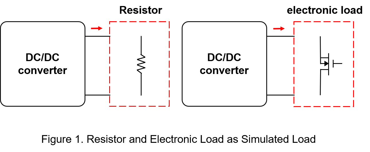
During load testing, as shown in Figure 1, resistors or electronic loads are typically used to simulate real-world load conditions.
Resistors establish a stable current load based on Ohm’s Law by maintaining a fixed resistance value, allowing for the measurement of circuit voltage and current.
Common types of resistors include carbon film resistors, precision resistors, metal oxide film resistors, and cement resistors.
For products that require a wide power range—such as power converters—cement resistors are often selected as test loads.
Electronic load instruments offer high flexibility, enabling the simulation of various load conditions and the absorption of different power levels to accommodate diverse testing requirements.
These devices support multiple operating modes, including constant current (CC), constant voltage (CV), constant resistance (CR), and constant power (CP).
Among these, CC and CR modes are commonly used when simulating the actual load conditions of a power converter.
Comparison Between Cement Resistors and Electronic Loads (CR Mode)
Cement resistors and electronic loads are both tools used for testing power supplies and electronic equipment, but they offer different functionalities:
(1) Cement Resistor
Resistors commonly used for load testing in power converters are high-power resistors, such as cement resistors and power wirewound resistors, as shown in Figure 2.
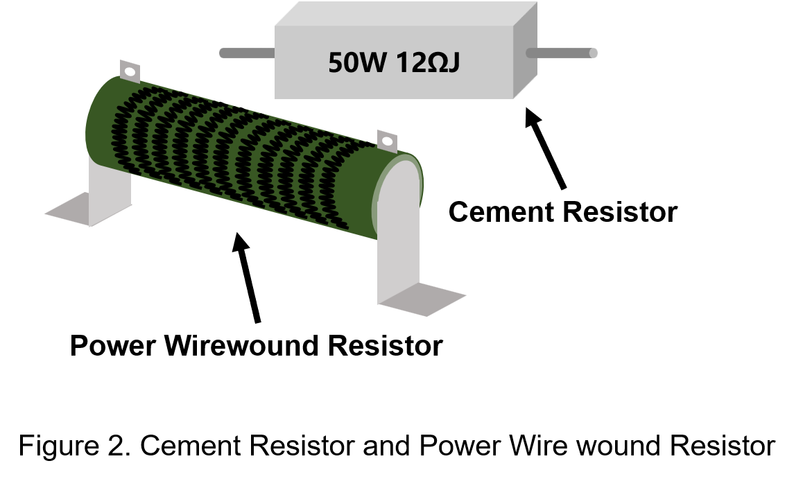
Cement resistors are filled and sealed with a special non-combustible, heat-resistant cement material.
Their advantages include a wide power range, low cost, a small temperature coefficient of resistance (TCR), and good linearity.
However, their disadvantages include large physical size, broader tolerance ranges, and heat dissipation issues in high-power applications.
The graph below compares the temperature coefficients of carbon film resistors and cement resistors.
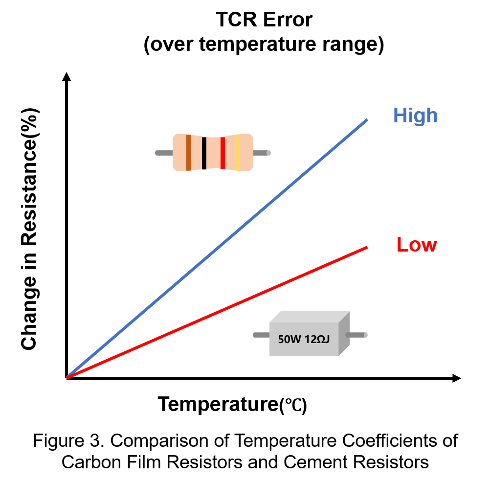
In high-power applications, heating issues are common, causing resistance values to drift as temperature increases, which can negatively affect measurement accuracy.
Therefore, the stability of the temperature coefficient of resistance (TCR) is critical.
Figure 3 illustrates that cement resistors exhibit smaller resistance changes—measured in ppm/°C—as temperature increases, compared to carbon film resistors.
(2) Electronic Load-CR Mode
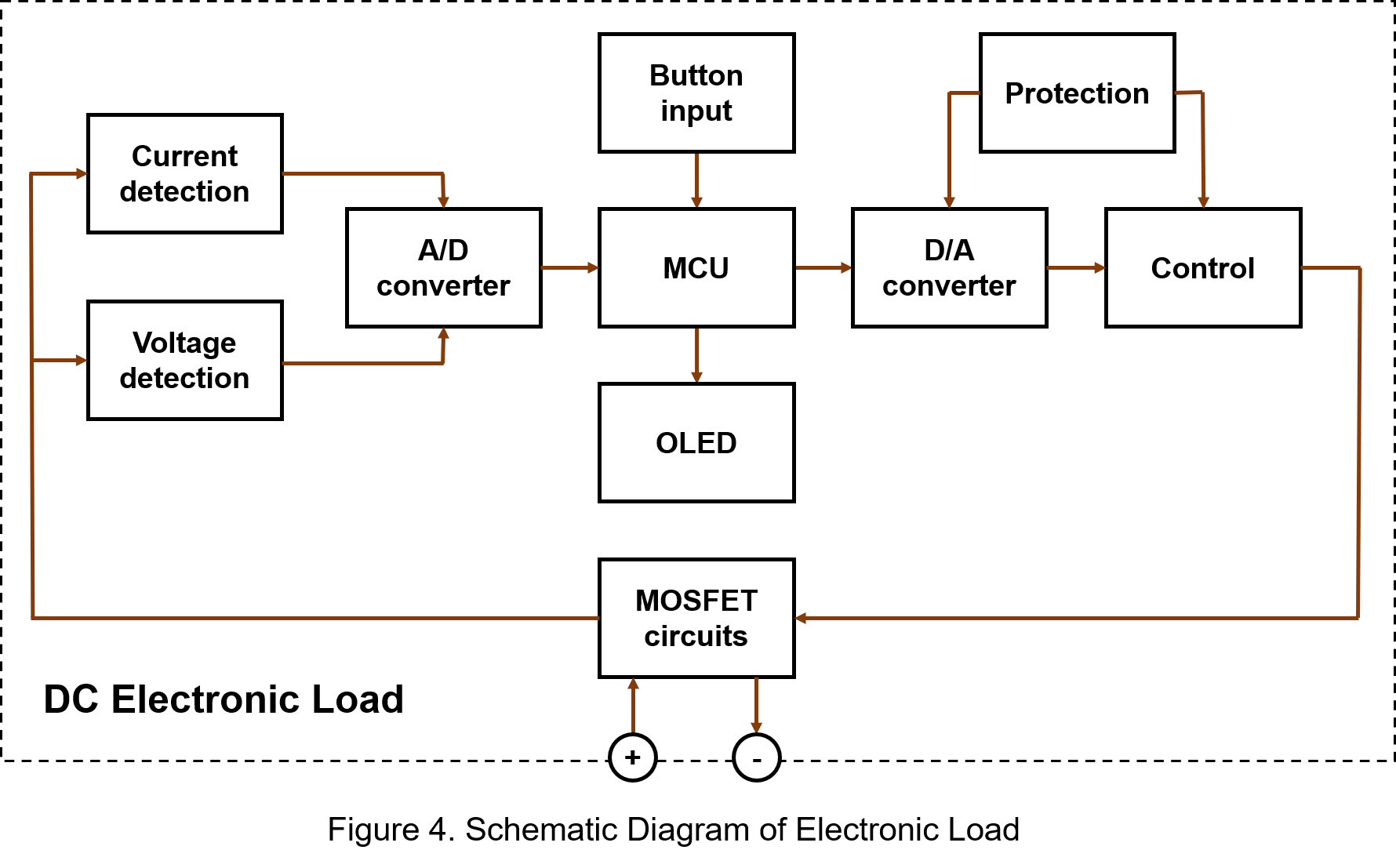
An electronic load is a device that regulates the conduction of power components, such as MOSFETs, to dissipate absorbed electrical energy as heat.
Its basic circuit architecture is shown in Figure 4.
When using an electronic load, the load can be adjusted instantly to meet different usage requirements.
This allows for rapid control of the power supply’s output current and ensures repeatable load conditions and consistent test results.
One of the most commonly used operating modes when testing power converters is the constant resistance (CR) mode.
The figure below illustrates the I–V characteristic curve of an electronic load operating in CR mode.
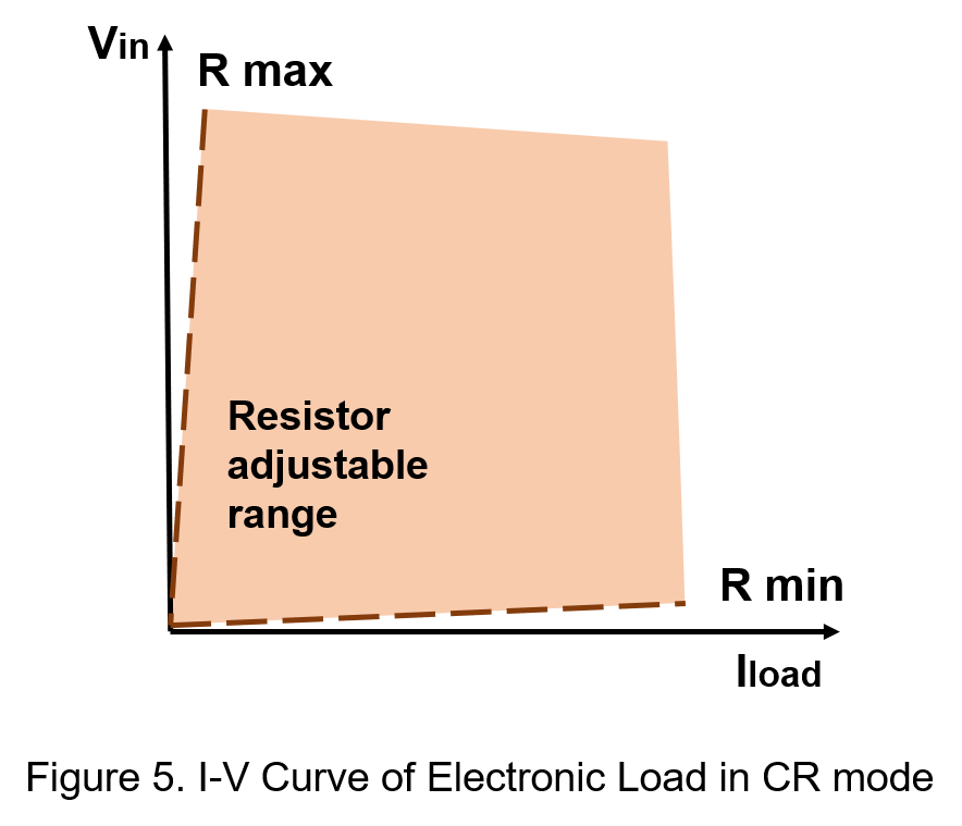
Figure 5 illustrates the operating characteristics of an electronic load in constant resistance (CR) mode.
In this mode, the voltage and current of the power load vary linearly along the resistance slope line.
The resistance value can be adjusted within a specified range—between R_min and R_max—as shown in the orange area of the power curve.
However, if the voltage or current exceeds the maximum power limit, the electronic load will automatically adjust its input settings to remain within the closest valid range.
By using CR mode, the electronic load functions as an adjustable power resistor, providing a stable and controllable load during power converter testing. It can effectively replace fixed resistors. When connected to a voltage source, the electronic load senses the input voltage and calculates the required current based on the set resistance value, thereby absorbing the power supply’s output to meet the desired load condition.
(3) Characteristic Differences
Due to their fixed resistance values and lack of adjustability, cement resistors are unable to simulate the dynamic load variations typical of real-world equipment under changing operating conditions.
Moreover, they cannot be integrated into automated control systems, limiting their suitability for use in automated test procedures.
In contrast, electronic loads can be easily adjusted to absorb varying power levels, making them significantly more flexible and adaptable.
The following table presents a comparison between the two types of load devices.
| Cement Resistor | Electronic Load (CR-Mode) | |
| Accuracy | Low | High |
| Heat Dissipation Requirement | High | Low |
| Heat Generation | Large | Small |
| Cost | Low | High |
| Series Connection | Yes | No |
According to the comparison table, the disadvantages of using resistors include:
1. Large resistance error, resulting in low measurement accuracy.
2. Inability to adjust test parameters in real-time; manual adjustments are time-consuming and reduce both testing efficiency and the level of automation.
3. Air-cooled heat dissipation requires larger physical space for installation.
In contrast, electronic loads can overcome these limitations and offer the following advantages:
1. Equipped with built-in thermal management systems, eliminating the need for external fans or large heat dissipation modules.
2. Capable of simulating constant current (CC), constant resistance (CR), constant voltage (CV), and short-circuit load conditions.
3. Higher degree of automation, significantly improving test efficiency and reducing manual labor.
It is worth noting that when the power output of the power supply exceeds the rated specification of a single cement resistor, multiple resistors with different resistance values can be connected in series or parallel to increase the total load capacity.
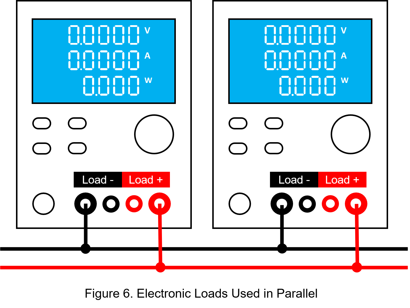
In the case of electronic loads, to increase rated capacity, two or more electronic load modules can be connected in parallel. However, care must be taken not to connect multiple electronic loads in series. Even if the units are of the same model, voltage distribution may become uneven due to small discrepancies between devices. This could result in one unit experiencing overvoltage and shutting down—or in severe cases, permanent damage.
Therefore, when using an electronic load, its functionality should be checked regularly and calibrated as needed to ensure safety and reliability.
Overall, for power testing that requires high repeatability, adjustable parameters, and automation support, electronic loads are the preferred choice.
However, for simple, steady-state high-power load simulations, cement resistors offer a more cost-effective alternative.
Testing in Real Scenarios
When testing power converters, both cement resistors and electronic loads have their suitable application scenarios.
Cement resistors offer advantages such as low cost, structural stability, absence of active switching components, and immunity to electromagnetic interference (EMI).
Electronic loads, on the other hand, provide fast response, precise load regulation, and programmable control, making them ideal for dynamic and high-precision testing.
Below is a classification of experiments suitable for each load type:
(1) Experiments Suitable for Cement Resistors
- EMI/ EMS Experiments: Cement resistors are passive components that do not involve switching operations or generate pulse noise.
As a result, they neither produce EMI nor are they sensitive to electromagnetic susceptibility (EMS).
This makes them highly suitable for electromagnetic interference (EMI) and electromagnetic susceptibility (EMS) testing, ensuring accuracy and consistency of test results.
This makes them highly suitable for electromagnetic interference (EMI) and electromagnetic susceptibility (EMS) testing, ensuring accuracy and consistency of test results.
- Static Tests: In efficiency or steady-state performance testing, cement resistors can serve as fixed-value loads that provide stable current absorption.
They are simple to operate and cost-effective, making them suitable for evaluating output characteristics under static conditions.
(2) Experiments Suitable for Electronic Loads
- Reliability Tests: Electronic loads allow precise control of current or resistance, making them ideal for reliability testing under extreme conditions such as high temperature and humidity.
They support stable, long-duration loading, enabling accurate assessment of power converter performance and durability in harsh environments.
- Dynamic Tests: Featuring fast response times, electronic loads can quickly switch between load states.This capability is especially useful in transient response testing and dynamic load variation analysis—such as simulating inrush current during startup or evaluating load regulation performance of a power supply.
Summary
This article compares two commonly used load methods in power converter testing: cement resistors and electronic loads in constant resistance (CR) mode. Cement resistors offer a simple structure and low cost, making them suitable for static load simulation or efficiency testing where high load accuracy is not required. In contrast, electronic loads provide programmable control, high precision, and fast dynamic response, making them ideal for advanced testing scenarios like transient response and dynamic behavior simulation.
Selecting the appropriate load method should be based on a comprehensive evaluation of test objectives and accuracy requirements to ensure valid and reliable results.
CTC is service provider for high-end power modules (DC to DC Converter and AC to DC Converter) for critical applications worldwide since 1987. We aim to be business generator and a virtual business unit. CTC is your own team with 35 years of experience for a strong business program from market research, product definition & development, supply chain management and total technical services.
CTC is the only corporation certificated with ISO-9001, IATF-16949, ISO22613(IRIS), and ESD/ANSI-2020. We can 100% ensure not only the product, but also our workflow and service to match quality management system for every high-end application from the very beginning. From design to manufacturing and technical support, every single detail is operated under highest standard.