

You are here
Back to topHow to increase energy efficiency of DC-DC converter?
With the increasing awareness of environmental protection, using high efficiency and low pollution products is the current trend. Electronics need to improve the conversion efficiency because each electronic product definitely cause energy loss. As long as the excess energy consumption can be minimized, the conversion efficiency can be improved. High conversion efficiency is an important direction of power supply design.
Following describes the various causes of energy loss and how to effectively improve converter efficiency, and the benefits of reducing static current.
1. Energy Depletion Methods
Whether in both operating mode and standby mode, the energy of power converter is lost through various paths, resulting in the efficiency become lower. Therefore, it is a major challenge to reduce energy loss. First, discuss and analyze the common parts of power converters where loss occurs.
Figure 1 shows a basic buck converter. The main sources of losses in a buck converter are presented as an example, including switching losses caused by power transistors, iron losses caused by inductors, losses caused by the equivalent series resistance of capacitors, and print circuit board layout. Common sources of loss are listed below.
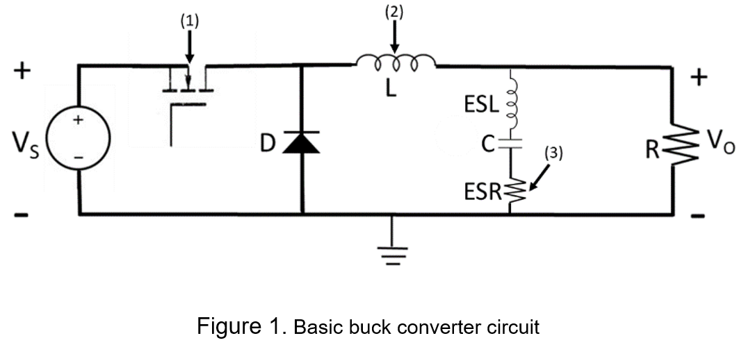
(1) MOSFET
The power consumption of the on-resistance flowing between drain and source of the MOSFET accounts for most of the losses in the power converter. The equation for the power consumption of the on-resistance is as follows:
![]()
where D is the duty cycle, Rds(on) is the on-resistance from draw to source and id is the draw current. Equation (1) shows that lower the on-state resistance, the lower the power consumption.
In addition, the on-resistance is related to the size of the MOSFET, so using the larger MOSFET can also effectively reduce the on-resistance.
The power consumption of the MOSFET is also affected by the operating frequency. To accomplish a better transient response, most power converters will use high-frequency switching, but it can make more severe the switching losses. As shown in the formula below.
![]()
Where fsw is the switching frequency of MOSFET, Eon is the turn-on loss and Eoff is the trun-off loss.
For power transistors, a common equation for power dissipation is equation (1) plus equation (2)
![]()
(2) Inductor
The inductor has the functions of energy storage and noise filtering in power converter. During the energy conversion process, the core loss of the inductor contains hysteresis-losses associated with the AC component and eddy-current losses associated with the frequency, and the higher frequency made the greater the eddy-current losses. The iron loss depends on the shape, material and construction of the inductor core, so it is important to select the correction of inductor for specification.
(3) Equivalent Series Resistance of Capacitors
The ideal capacitor would not suffer from any energy loss, but the material of the capacitor still has a resistance value in mΩ. But when a large current flowing, causes considerable power loss. The equivalent series resistance can be reduced by connecting the capacitors in parallel.
(4) Printed Circuit Board Layout
The copper foil resistance of the printed circuit board circuit has a resistance value of about mΩ. For the large current path, a small resistance at both ends of the copper foil circuit can cause signal attenuation. Therefore, the resistance of the copper foil needs to be evaluated. The equation for the resistance per unit area of copper foil is as follows:
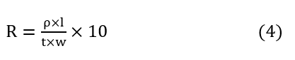
Where l is the length of conductor[mm], w is the width of conductor[mm], t is the thickness of copper foil[µm], and ρ is the resistivity of the copper foil, which is given by
![]()
Where T is the temperature[°C]. The resistance per unit area of copper foil can be derived from equation (4). For example, l and w are both calculated as 1 (mm) and t is 50 (um).Table 1 shows the resistance per unit area of copper foil.
|
Temperature (°C) |
-25 | 0 | 25 | 50 | 75 |
|
Resistance (mΩ) |
0.27 | 0.31 | 0.344 | 0.377 | 0.41 |
1.1 How to Reduce Converter Losses
It is important to select the correct power switching components and passive components, and then reducing internal resistance improves conversion efficiency. For example, selecting silicon carbide (SiC) process components, which has almost no switching losses and high temperature resistance may provide higher efficiency; larger the size of MOSFETs can be used to achieve lower on-resistance; parallel connection of several capacitors to reduce the equivalent series resistance and reduce the length of high current path and increase the width of the high current path to lower the resistance of the copper foil.
2. Benefits of Reducing Static Current
When electronic products are in a state of standby or light load for long time, most products still rely on battery power such as mobile phones in standby mode and the battery when the car is turned off.
When the system has no external input signal, the current consumed by the converter in the steady state is called the quiescent current. Reducing the quiescent current can extend the life of the battery and improves efficiency at light loads. Therefore, reducing the quiescent current is important for energy loss.
2.1 How to Reduce Static Current
Reducing the quiescent current is a difficult issue. During the design phase, it is necessary to analyze the on-resistance of each pin in standby mode, use transmission gate as a switching circuit which has low on-resistance and high cut-off resistance, to reduce the switching frequency in standby mode, to choose a chip with a low quiescent current, and to provide a low voltage to wake up or switch off the power converter function, for example, 3.3V input voltage can turn off the circuit. The above methods can effectively reduce the quiescent current.
3. Conclusion
The concept of a low-carbon living environment is rapidly grown in the world, it is important to find ways to design more energy-saving electronic products, especially electronic products have lower quiescent current under light load and standby mode to extend battery life and achieve energy saving. If wanting to design more energy-saving products, it can change from the selection suitable components and designing circuit can also effectively reduce the unnecessary components and metal-line losses.
In addition to the choice of components, the circuit design can also be effective in reducing the number of unnecessary components and circuit losses.
CTC is service provider for high-end power modules (DC to DC Converter and AC to DC Converter) for critical applications worldwide since 1987. We aim to be business generator and a virtual business unit. CTC is your own team with 35 years of experience for a strong business program from market research, product definition & development, supply chain management and total technical services.
CTC is the only corporation certificated with ISO-9001, IATF-16949, ISO22613(IRIS, AFNOR silver certificate), and ESD/ANSI-2020. We can 100% ensure not only the product, but also our workflow and service to match quality management system for every high-end application from the very beginning. From design to manufacturing and technical support, every single detail is operated under highest standard.