

You are here
Back to topImprove System Reliability with Converter Redundancy
As market applications become more and more diverse, systems with high power sensitivity require a more stable power supply, such as industrial servers and medical-related applications. When the main converter fails, the backup power supply can provide emergency power for the load equipment, reducing the risk of system failure and increasing reliability. This article will introduce design considerations for redundant systems and the feature of different architectures.
1. Introduction
Backup system can also be called a redundant system. In order to improve system reliability, a duplicate system is deliberately set up. The function is that when the main converter fails and has no output, the backup converter can be quickly replaced. The two converters are independent of each other, and the probability of failure at the same time is quite low, so setting up a redundant system can avoid system failures. This feature can be achieved using a power multiplexer, followed by an introduction to the topology and design considerations of the power multiplexer.
2. Power Multiplexer
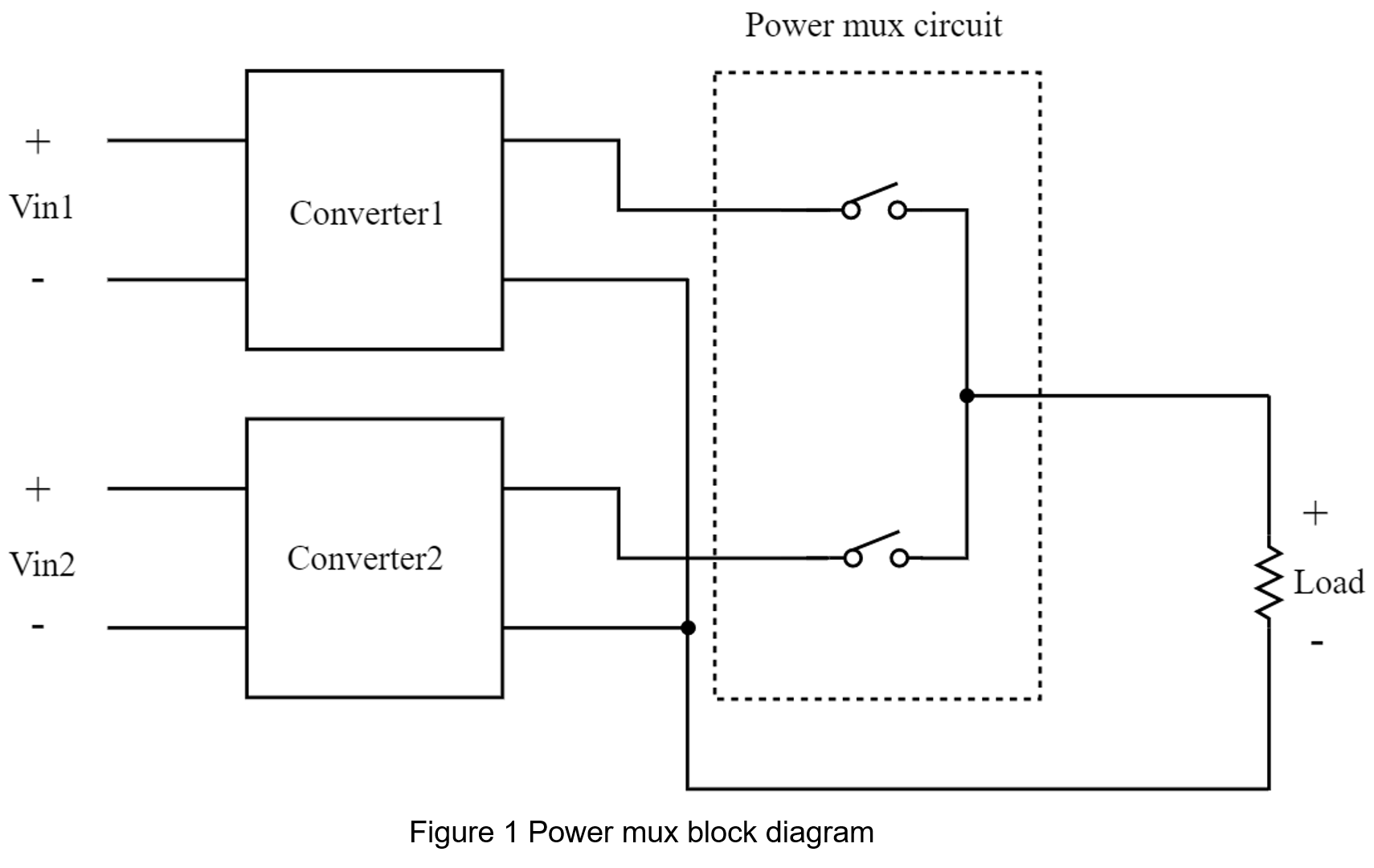
As shown in Figure 1, power multiplexer is a set of electronic switches that can switch between two input power supplies to provide the same output and prevent reverse current between the two power supplies.
2.1 Design Considerations
The ideal feature of power multiplexer is that when the current flows through the switches, which can be sent to the load without loss, and the ideal switching time is close to zero. The power multiplexer is to achieve the function of the redundant system. It is also an important goal to avoid the redundant converter and the main converter to work at the same time. Reducing the probability of simultaneous failure and achieve the goal of improving reliability. The less of components in the external circuit the better, so probability of system failure will be relatively reduced.
- Voltage Drop
Power multiplexer uses electronic switches to select the input sources. The voltage drop generated by the current flowing through the electronic switch. Different switches will make different in voltage drop.
- The advantage of using a diode as a switch is that it switches very quickly and doesn't require any control circuit. But diode has a voltage drop about 0.7V.
- Using MOSFETs as switches has the advantage of low voltage-drop. But MOSFETs require additional control circuit.
- Switching Speed
The switching speed refers to the time for the main power supply switches to the redundant power supply. The time is longer, and lets the load is switched to the redundant converter to be later, and then the larger the output voltage drop will be. In order not to cause the main system to stop due to the low voltage during the switching process, special consideration must be given to the design.
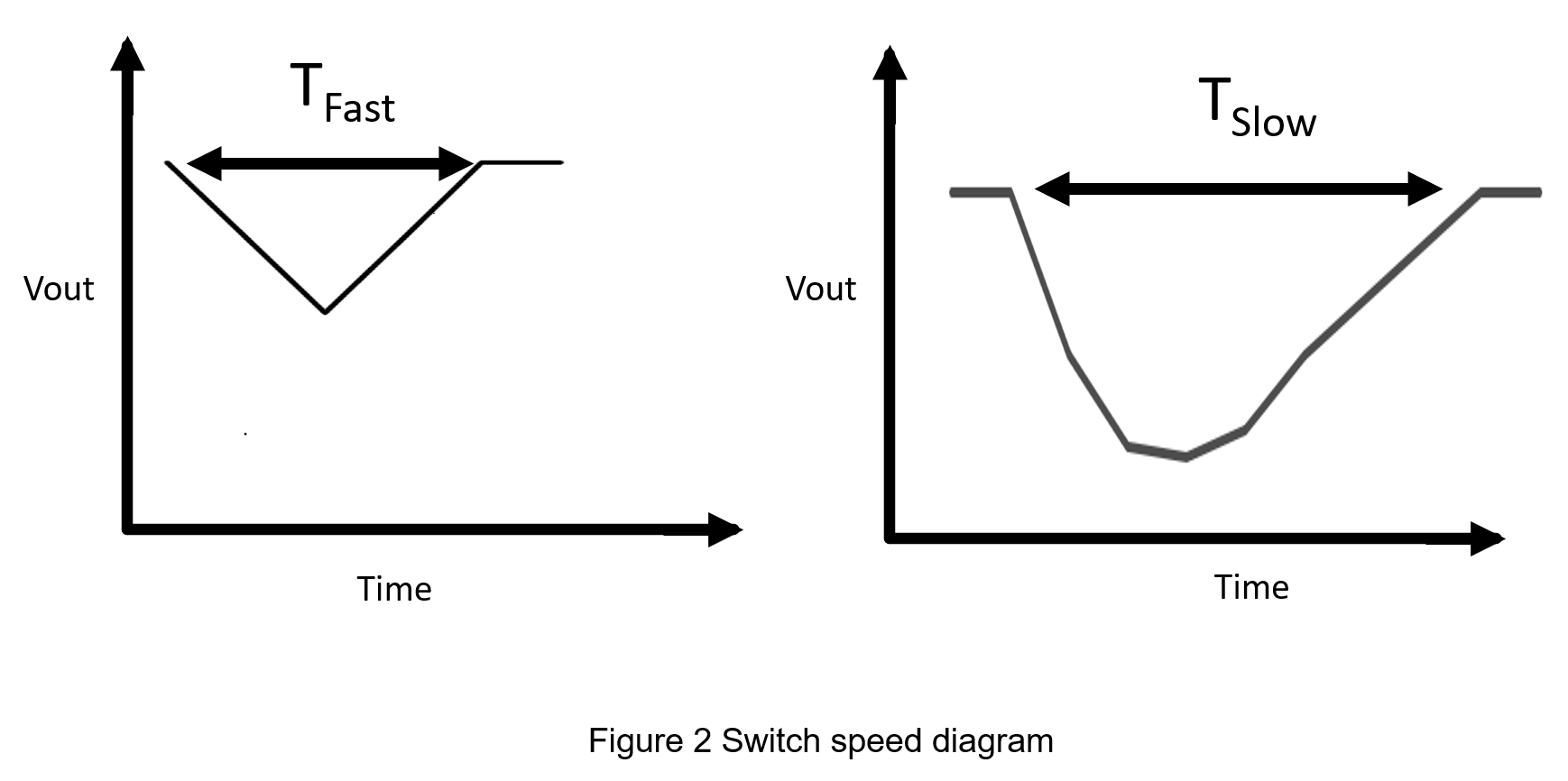
Figure 2 shows the process of switching the main power supply to the redundant power supply. Since the redundant converter has not yet started, a voltage drop begins at the load. The longer the switching time, the greater the voltage drop. However, the simultaneous operation of the redundant converter and the main converter increases the probability of failure at the same time.
3. Power Multiplexer Topologies
The architecture selection of power multiplexing is mainly based on applications. As a redundant system, it is necessary to consider the switching time and the number of additional components, and then select architecture according to the system power.
3.1 ORing Diode
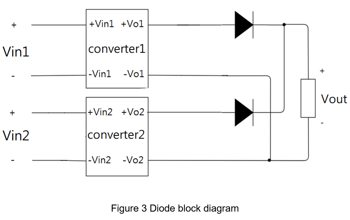
The easiest redundant method is using oring diodes, the fastest switching speed and least external components, but the disadvantage is that the voltage drop of the diode will continue to generate power loss during conduction, causing high temperature, so it is only suitable for low-power applications. High-power applications need to reduce the problem of heat which is build-up from voltage drops.
3.2 Remote On/Off Method
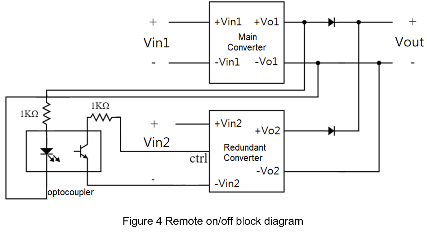
Connect the output of main converter to the control pin of the redundant converter. When the main converter works normally, the redundant converter will state in the standby mode and the main converter for output only. On the other hand, when the main converter fails, the redundant converter will start soon. The advantage of this method is that the redundant converter does not consume any power under normal operation, and if the optocoupler fails, the system is still a diode structure, which will not affect the power supply to the load. The disadvantage is that the switching time is the slowest of all methods due to the limitations of the remote function.
3.3 Single MOSFET Switch
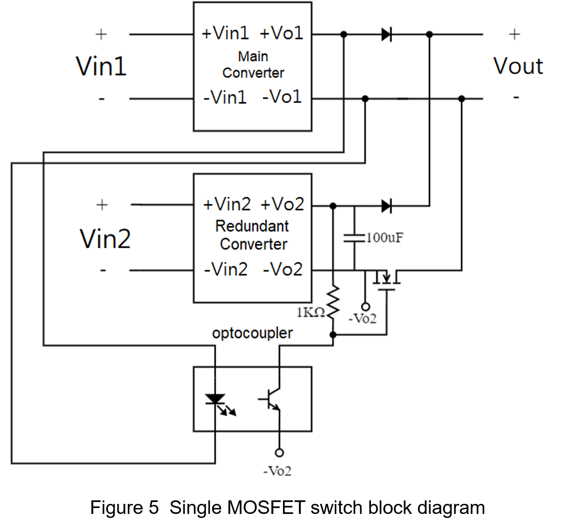
Optocoupler isolator and an N-type MOSFET are used as switching components. Adding capacitors at the output of the redundant converter to avoid transient response to change suddenly. The advantage of this architecture is that the switching time is short. Because of the architecture is simple, high-power applications only need to replace MOSFETs and capacitors that can match the specifications. The disadvantage is that there is no scalability, it is limited to main converter with only one redundant converter instead of multiple, and when the MOSFET fails, the entire backup system cannot work.
3.4 Digital Control Logic Switch
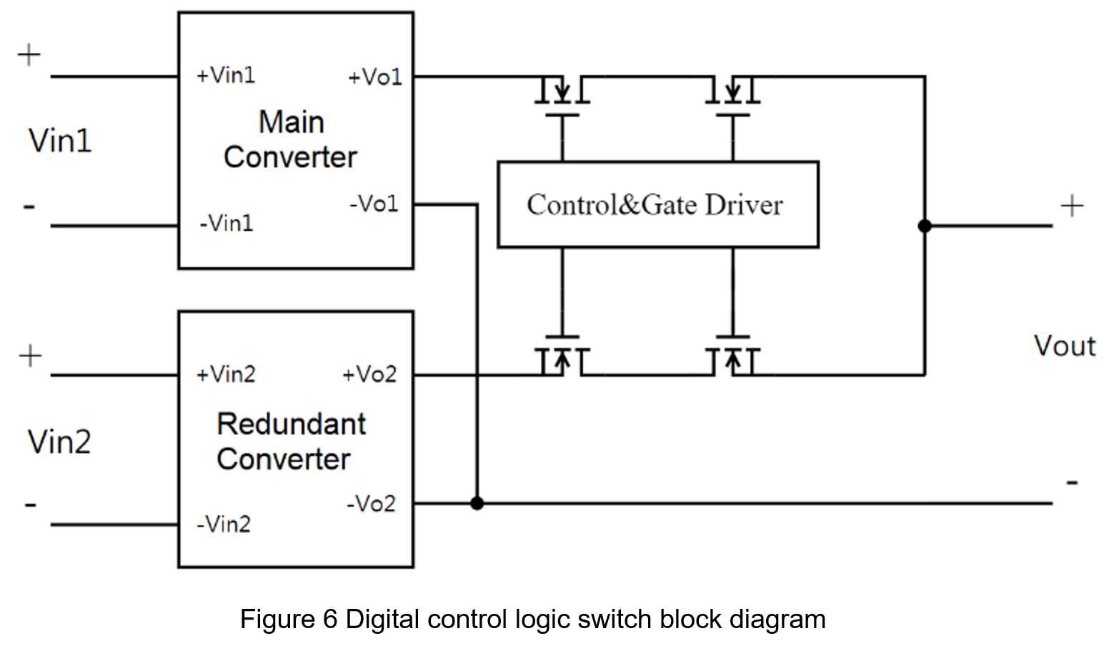
Digital logic switches can prevent reverse current without diodes, and then reduce voltage drop. However, in order to avoid two sets of MOSFETs from turning on at the same time and causing excessive current, dead time must be designed. It means that switching time of this method is relatively long. This architecture is not suitable for power multiplexer for redundancy purposes.
The purpose of redundant system is to increase reliability, so the less components in circuit is better to avoid an overly complicated structure. Because that he more components, the more chances the circuit fails. Therefore, this article chooses the remote on/off and single MOSFET architecture to compare its advantages and disadvantages.
4. Application
This article chooses the remote on/off and single MOSFET architectures to achieve power multiplexer for redundant purposes.
4.1 Remote on/off
The converter with remote control function makes the converter in standby mode or restart through the control pin (CTRL). The control configurations can divide into positive logic and negative logic. Positive logic means that the control signal is high, and the converter operates normally. Negative logic means that the control signal is low, and the converter operates normally.
4.2 Experimental Condition
The following table shows the specifications of the DC/DC power converter for this experiment.
| Output Power | 60W |
| Input Voltage | 9-36Vdc, Nom.24Vdc |
| Output Voltage | 5Vdc |
| Output Current (full load) | 12A |
| Efficiency (typ.) | 91% |
4.3 Result
Remote on/off architecture
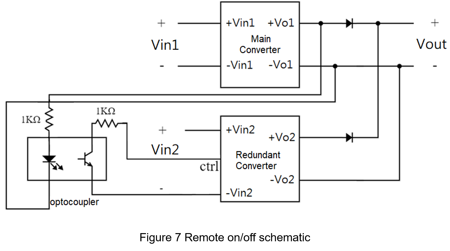
This circuit uses the output of the main converter to shutdown down the output of the redundant converter, and uses an optocoupler to isolate the two circuits. The switching speed is limited by the specifications of the converter itself.
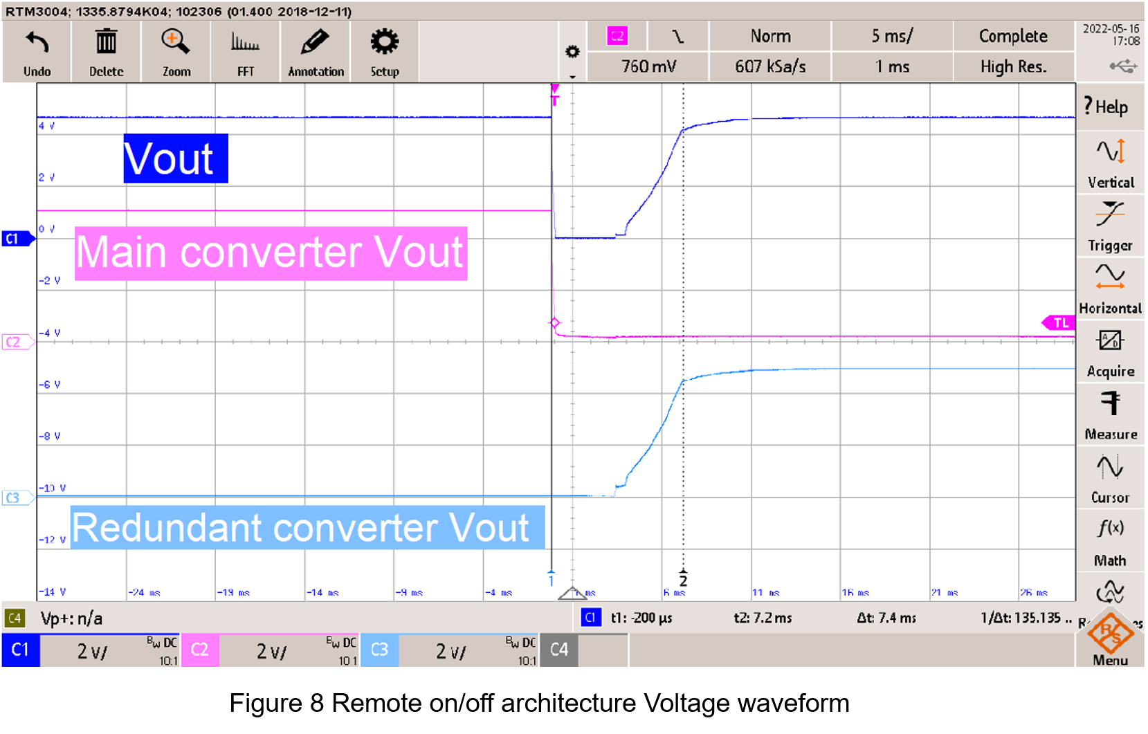
According the result in figure 8, the switching time is 7.4ms. During switching process, there is no output for nearly 5ms. To reduce the switching time, the solution is using faster response converters.
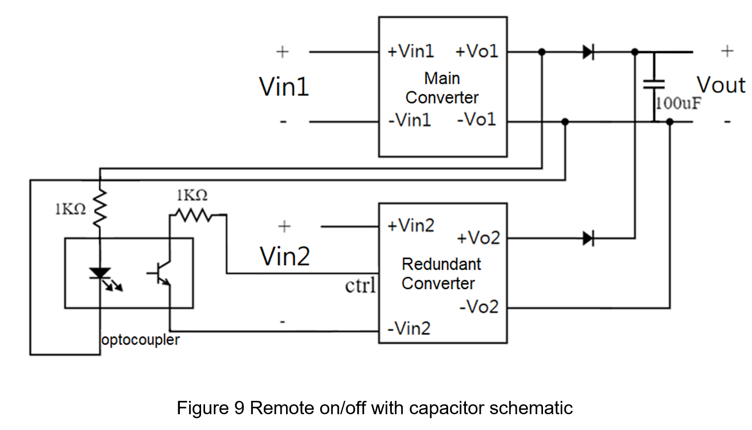
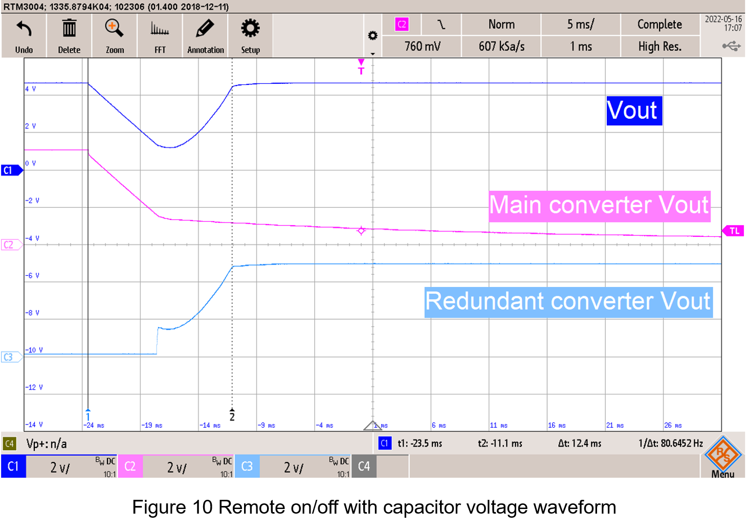
Although adding a capacitor at the output can reduce the voltage drop during the switching process, it also increases the turn-on time of the redundant converter because the output voltage of the main converter is decreasing slowly. The switching time increased from 7.4ms to 12.4ms.
Single MOSFET switch architecture
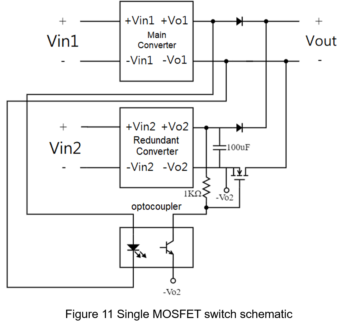
This circuit also uses the main converter to shut down the redundant converter, but the switch uses MOSFET, which has a faster switching speed, and increases the capacitance at the backup output to improve the transient response.
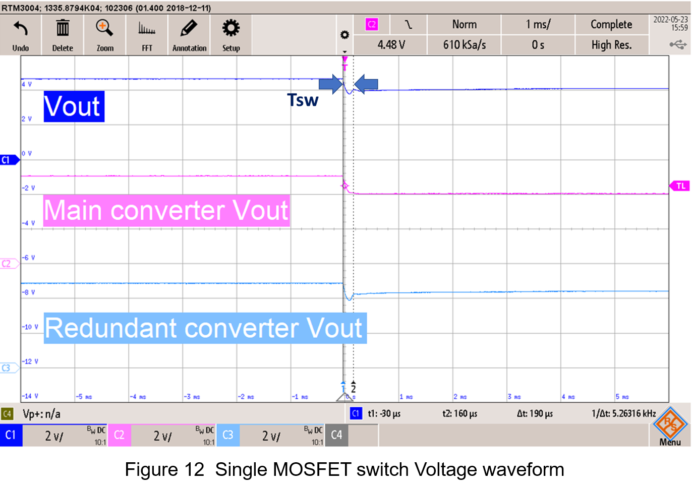
According the result in figure 12, the switching time is 190us, and the output voltage drop during the conversion is about 0.4V, which fits the requirements of short switching time and low voltage drop. Because the redundant converter passes through a MOSFET, there will be a voltage drop about 0.2V after the voltage reaches steady state. It can be improved by using lower RDS(on) MOSFET, or using the output voltage trim function.
5. Conclusion
This article introduces several factors to improve reliability, and analyzes the advantages and disadvantages of power multiplexer architectures to find out which ones are suitable for redundant system. It is confirmed after experiments that a single MOSFET architecture is the most suitable because that transient time and forward voltage drop are acceptable.
CTC is a professional service provider for high-end power supply modules (AC to DC Converter and DC to DC Converter) for critical applications worldwide since 30 years. Our core competence is to design and deliver products with leading technologies, competitive pricing, extremely flexible lead-time, global technical service and high-quality manufacturing (Made In Taiwan).
CTC is the only corporation certificated with ISO-9001, IATF-16949, ISO22613(IRIS), and ESD/ANSI-2020. We can 100% ensure not only the product, but also our workflow and service to match quality management system for every high-end application from the very beginning. From design to manufacturing and technical support, every single detail is operated under highest standard.