

You are here
Back to topThe Importance of Hold Up Time for Railway Applications
In railway system, the power source of train cabin can be roughly divided into three types. One is using pantograph collect the electric energy, and transfer to the system by static converter. Second is generator set to provide the electric energy. The third one is through battery management system to provide power.
The common voltage of railway system is 24V, 72V and 110V. When the power source module of the train is converted, the power supply on the train is prone to variations, such as a sudden voltage drop or a temporary absence of power. In this regard, EN 50155 has special definition.
1. The requirement of EN50155.
The EN50155 have two requirement of input voltage variation. The first one is interruptions of voltage supply.
There are several conditions that the system input voltage may be affected. Like, the power source overload or fault condition, or the re-power operation after the operation of the fuse or short circuit. The system input voltage may be drops to 0V in a short time, or presents a low-impedance condition.
The converter shall operate normally after the voltage interruption, it can meet the specification of S1. When the input voltage drops to 0V and returns to normal after 10mS, the system remains stable. It meets the specifications of S2. In addition, the input voltage drops to 0V for up to 20mS, and if the system remains stable, it meets the specifications of S3.
| Class | Requirements |
| S1 | In Case of voltage interruption, no performance criterion is requested but the equipment shall continue to operate as specified after the voltage interruption. |
| S2 | In case of voltage interruption up to 10 mS the equipment shall behave according to performance criterion A. |
| S3 | In case of voltage interruption up to 20 mS the equipment shall behave according to pweformance criterion A. |
Table 2 shows the specifications for output voltage variation during power supply change-over. When the input voltage drops to 0.6 times the steady-state input, the system remains stable, then it meets C1. When the input voltage drops to 0V and returns to normal situation after 30mS, the system remains stable. In this condition, it meets the specifications of C2.
| Class | Requirements |
| C1 | At 0.6*Vin duration 100 mS (without interruptions). Performance criterion A. |
| C2 | During a supply break of 30 mS stating at Vin. Performance criterion B. |
Table 3 shows the pass and fail criteria, which are mainly divided into four levels. The criteria A and B means acceptable, and criteria C and D means not acceptable.
| Criteria | Requirements | Result |
| A | Normal performance within limits specified by the manufacturer. | Pass |
| B | Temporary loss of function or degradation of performance. Self-recovery after the test, without operator ontervention. | Pass |
| C | Temporary loss of function or degration of performance. Operator intervention needed for recovery after the test. | Fail |
| D | Loss of finction or degradation of performance which is not recoverable. | Fail |
2. The Common Method
Most of the train equipment have built in dc/dc converter, and the purpose of the converters is to convert the power supply to the internal required voltage. In order to meet the requirements of the system to maintain normal operation when the input power is interrupted. Adding additional capacitors is required at the input side of any DC/DC converter. And the value of capacitor can be calculated by the following formula:
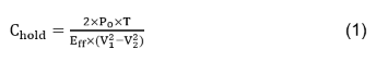
Po : Converter Output Power.
T : Maintenance Time.
Eff : Efficiency of Converter.
V1 : Normal input voltage.
V2 : Converter Lock-out Voltage.
For example, the converter has an output power of 30W and an efficiency of 91%. The normal voltage is 24V, the lock-out voltage is 8V, and the expected maintenance time is 10mS. According to the formula, the capacitance value is 1288uF.
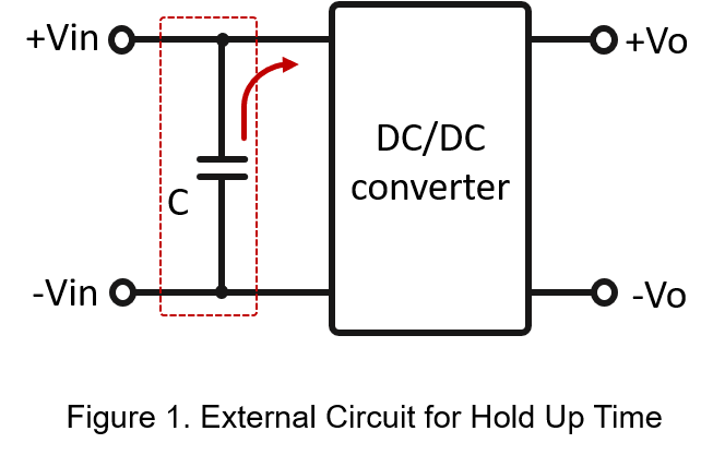
If connect capacitor to the input source with no external current limit circuit, it will generate a large surge current when the input voltage turns on. Which may cause the front-end power supply voltage drop or enter protection mode. At this time, just to connected resistor and diode in series with the capacitor input side. The inrush current can be alleviated. When DC bus is charging to the capacitor through resistor, so the inrush current can be limit. However, when the DC bus needs power, the capacitor can feed the power back to the DC bus through diode.
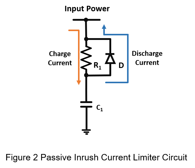
It can be seen from the figure that R1 is inversely proportional to the inrush current, so it can be calculate R1 by the following formula:
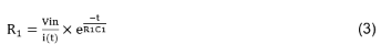
I: Inrush current.
Vin: Input voltage.
Loss on R1
![]()
t: Can be roughly regarded as a double time constant
![]()
Loss of resistance can be obtained by taking formula (4)
3. Test Result
Figure 3 is the schematic of hold up time circuit. The Converter Lock-out Voltage is 8V, the Eff is 91%, the output power is 60W, and the hold up time is 20mS.
But, the energy of CHOLD must be transmitted through D2. Diode has a turn-on voltage drop, which must also be taken into account when calculating. Therefore, the cut-off voltage must be increased from 8V to 9.2V. It can be calculated by formula 1 that CHOLD must be externally connected to 2683uF. So, take CHOLD is 2700uF and the peak value of the inrush current is 4.55A, and R1 can be calculated as 5ohm by formula 2.
The purpose of D1 is to prevent the input reversed diode.
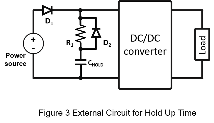
The following table shows the spec of the DC-DC power converter and the external components.
| DC/ DC Converter | PC60WR42412 |
| Vin | 24 Vdc |
| Vo/Io | 12 Vdc/5A |
| CHOLD | 2700 uF |
| R1 | 5Ω |
| D1 & D2 | V10P10 |
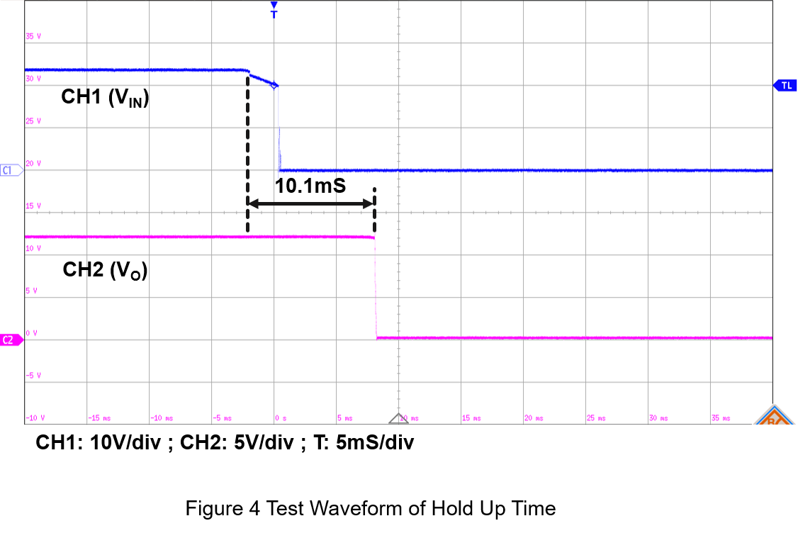
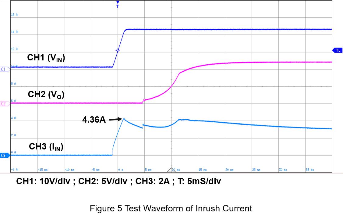
As Figure 4 shows, when the input voltage drops from 24V to 0V, the converter continues to supply power through CHOLD. And the output voltage maintains about 10.1 mS, which can meet the S2 specifications. And Figure 5 shows the inrush current is about 4.36A, which also similar as the calculated result.
Summary
In railway applications, the external capacitor for hold up time is very important. Also, need to pay attention to limit the inrush current. This article shows the calculated for external circuit and measure the test waveform. Make sure the system or converter can meet the hold up time requirements of railway applications.
CTC is a professional service provider for high-end power supply modules (AC to DC Converter and DC to DC Converter) for critical applications worldwide since 30 years. Our core competence is to design and deliver products with leading technologies, competitive pricing, extremely flexible lead-time, global technical service and high-quality manufacturing (Made In Taiwan).
CTC is the only corporation certificated with ISO-9001, IATF-16949, ISO22613(IRIS), and ESD/ANSI-2020. We can 100% ensure not only the product, but also our workflow and service to match quality management system for every high-end application from the very beginning. From design to manufacturing and technical support, every single detail is operated under highest standard.