

You are here
Back to topEMI Recommend External Circuit_Radiation
Electromagnetic compatibility (EMC) can be divided into two parts, one is Susceptibility the other one is Interference. Electronic device needed to meet the specifications of EMI and EMS with different application requirement. Which means that the device must include corresponding countermeasures during the design process, whether it requires external components or not. Previous articles have described the conduction part, this article focus on the radiation part.
1. Common External Circuit for EMI
Except to ensure the PCB layout can meet the internal requirement of each company. The most common methods is using safety capacitors to suppress noise. The connection of safety capacitors is line-to-line and line-to-ground.
The safety capacitor means when the capacitor fails, it still can guarantee the galvanic isolation. And it would not put humans in danger. Safety capacitors include X capacitors and Y capacitors. The X capacitor is connected across the line to the line, and is commonly used in AC/DC converter. The Y capacitor is connected across the line to line and line to ground, and is used in AC/DC or DC/DC converter.
Table 1 shows the types of X and Y capacitors:
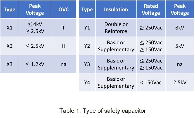
As table 1 shows, the difference is the isolation voltage capability. In order to avoid the leakage current when the input or output is connected to the ground, the capacitance of Y capacitor does not exceed 0.1uF.
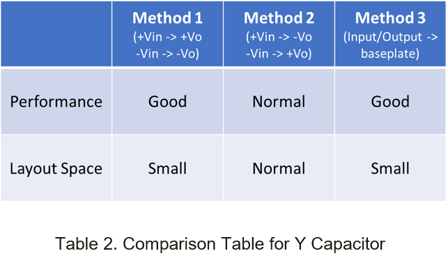
There are three common ways to use safety capacitors:
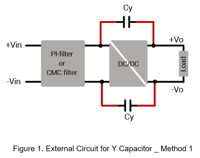
- Connect between primary and secondary side. (+Vin to +Vo / -Vin to -Vo)
The most common method for radiation is connecting Y capacitor across converter +Vin to +Vo and -Vin to -Vo. The main purpose is to release the high-frequency switching or common mode noise on the primary side to the secondary side. Through the Y capacitor, it can avoid radiation noise spread through the input line.
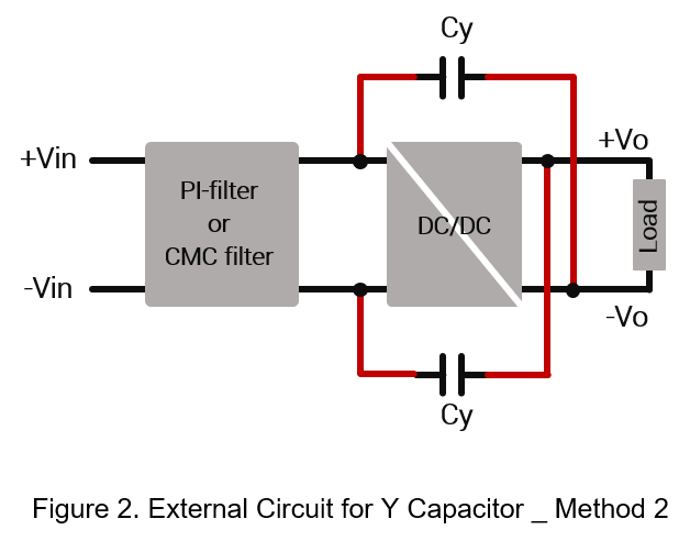
- Connect between primary and secondary side. (+Vin to -Vo / -Vin to +Vo)
Connecting Y capacitor across converter +Vin to -Vo and -Vin to +Vo. Same as method 1, the main purpose is to release the high-frequency switching or common mode noise on the primary side to the secondary side.
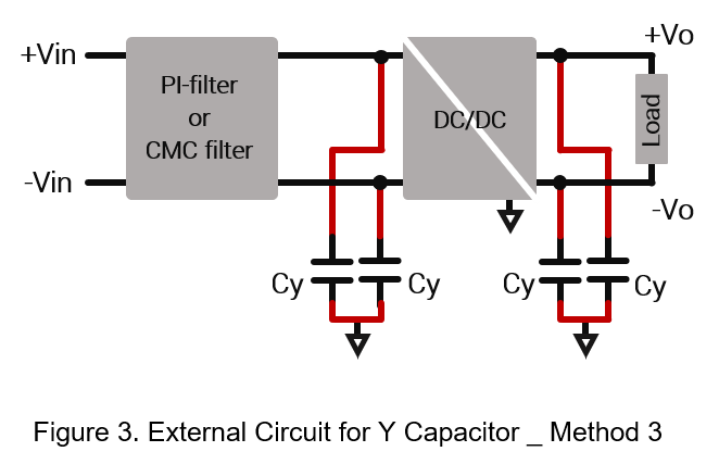
- Connect between primary or secondary side to base plate. (Input / Output to baseplate)
For converters with aluminum baseplate, in addition to connecting Y capacitors between the input and output side, it also connected Y capacitors to the aluminum baseplate across the input or output side, as shown in Figure 3.
2. Test Result
Next step will use dc/dc converters and Y capacitor which mentioned in Figures 1 and 2 to do the test result.
- Converter 1:
Input Voltage: 24V
Output Voltage: 5V
Output Current: 3A
Operation Frequency: 350kHz
Figure 4 shows the test result without Y capacitor. It can be seen that the main radiation noise is in 30~200MHz.
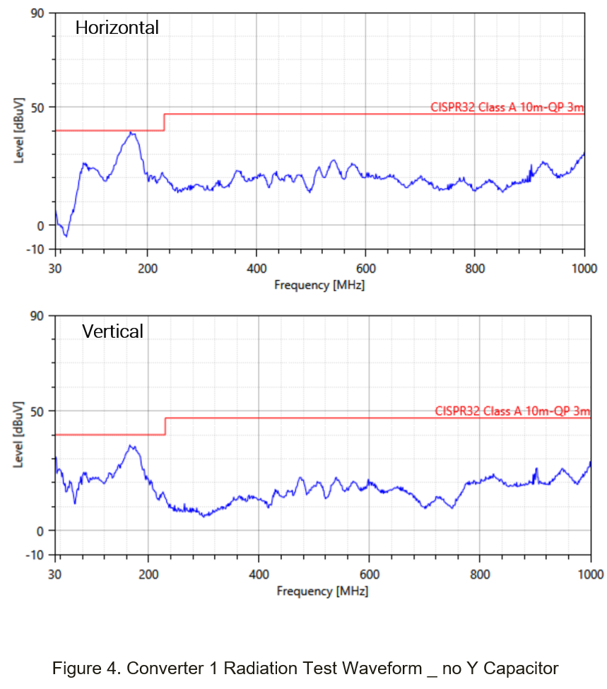
Figure 5(a) shows the external circuit of method 1, the input filter is PI filter. The C1, C2 are 4.7uF (50V, 1206, MLCC), L1 is 4.7uH (TMPA0605S-4R7MN-D). The Y capacitor Cy1, Cy2 is 1500pF.
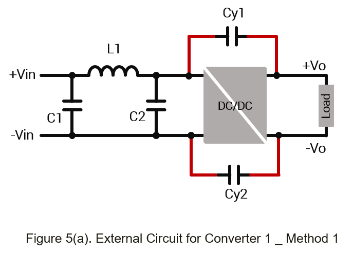
Figure 5(b) is the test waveform. Compared with Figure 4, it can be seen that the noise from 30MHz to 200MHz has a downward trend.
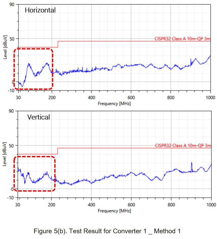
Figure 5(b). Test Result for Converter 1 _ Method 1
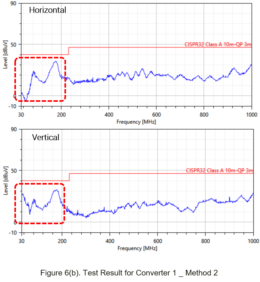
Figure 6(a) shows the external circuit of method 2, the input filter is PI filter. The C1, C2 are 4.7uF (50V, 1206, MLCC), L1 is 4.7uH (TMPA0605S-4R7MN-D). The Y capacitor Cy1, Cy2 is 1500pF.
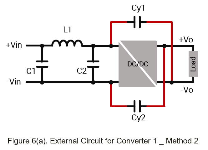
Figure 6(b) is the test waveform. Compared with Figure 4, we can find the noise slightly drop in 30~200MHz. Compare with Figure 5(b), the effect is not good.
Next step will use dc/dc converters with baseplate and Y capacitor which mentioned in Figures 1 to 3 to do the test result.
- Converter 2:
Input Voltage: 110V
Output Voltage: 12V
Output Current: 5A
Operation Frequency: 250kHz
Figure 7 shows the test result without Y capacitor. It can be seen that the main radiation noise is in 30~200MHz.
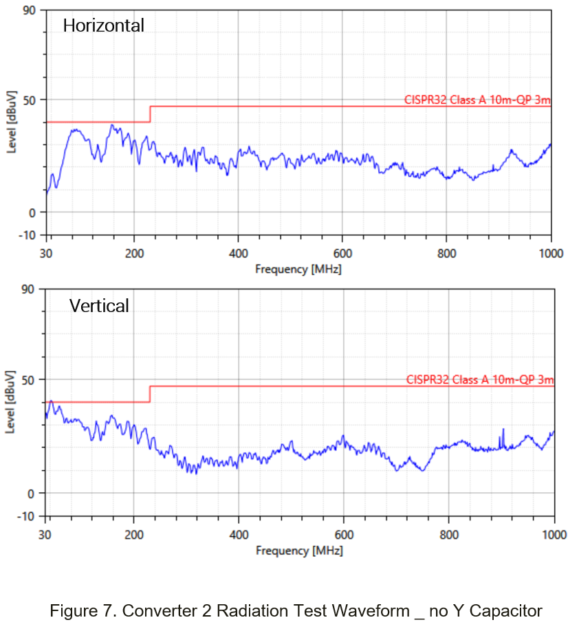
Figure 8(a) shows the external circuit of method 1, the input filter is PI filter. The C1, C3 are 100uF (200V, E-Cap), C2, C4 are 0.68uF (200V, 1210, MLCC), L1 is 10uH (GSTD1265PE-100M). The Y capacitor Cy1, Cy2 is 1000pF.
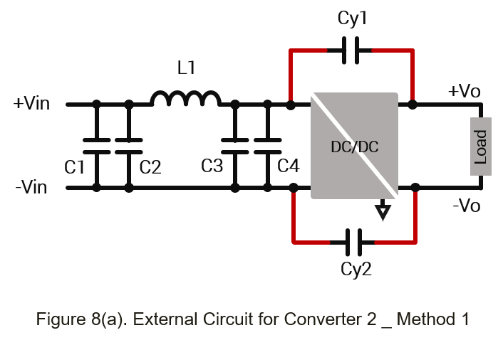
Figure 8(b) is the test waveform. Compared with Figure 7, we can find the noise slightly drop in 30~200MHz.
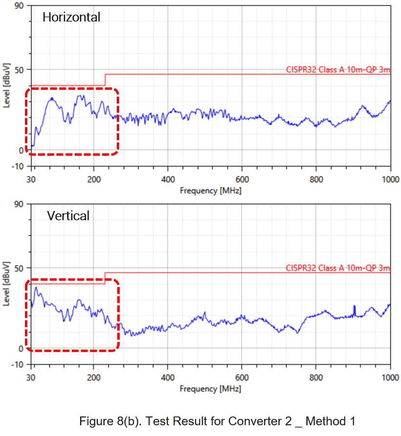
Figure 9(a) shows the external circuit of method 2, the input filter is PI filter. The C1, C3 are 100uF (200V, E-Cap), C2, C4 are 0.68uF (200V, 1210, MLCC), L1 is 10uH (GSTD1265PE-100M). The Y capacitor Cy1, Cy2 is 1000pF.
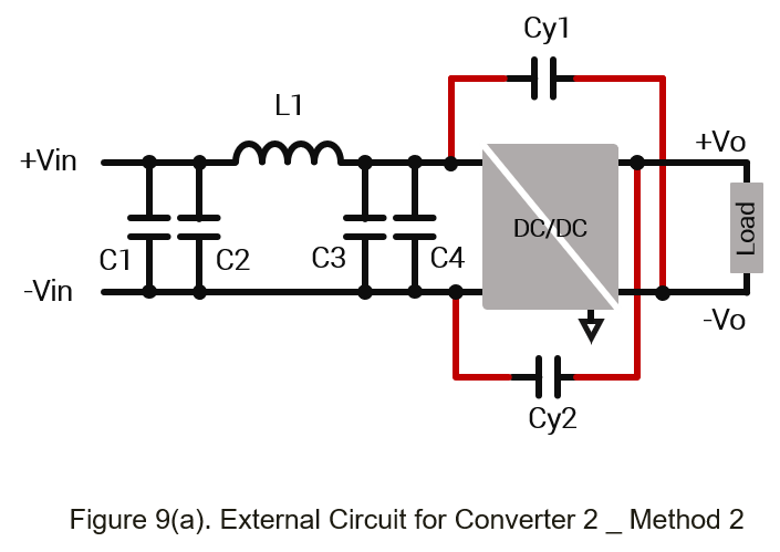
Figure 9(b) is the test waveform. Compared with Figure 7, we can find the noise slightly drop in 30~200MHz. Same as Method 1, the result is not good.
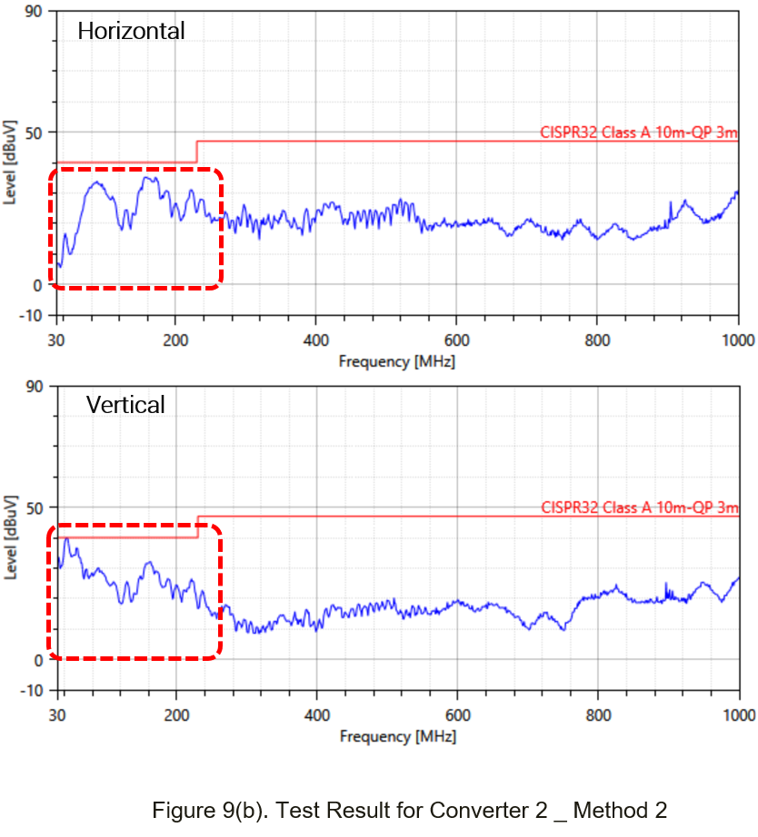
Figure 10(a) shows the external circuit of method 3, the input filter is PI filter. The C1, C3 are 100uF (200V, E-Cap), C2, C4 are 0.68uF (200V, 1210, MLCC), L1 is 10uH (GSTD1265PE-100M). The Y capacitor Cy1~ Cy2 is 1000pF.
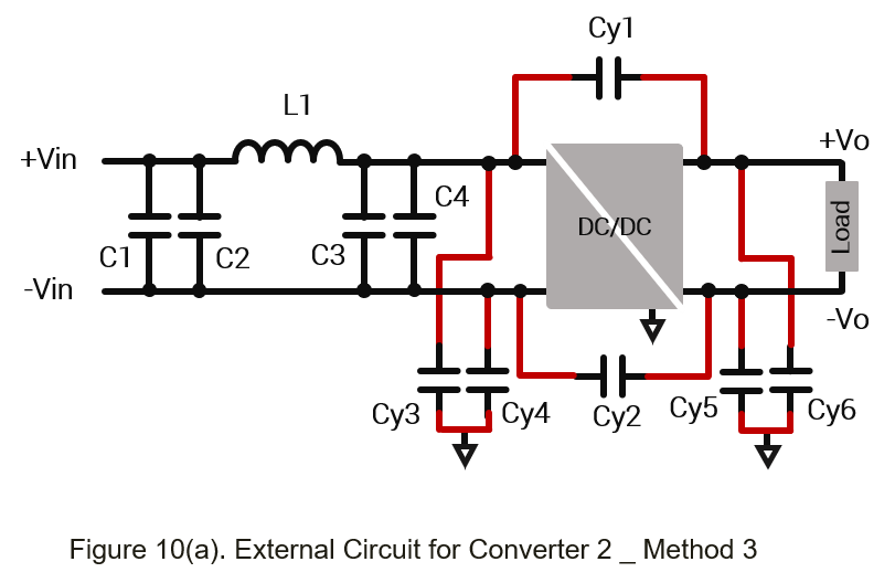
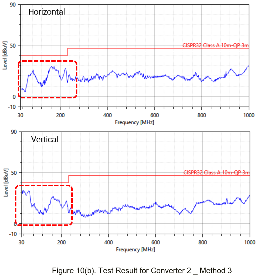
Figure 10(b) is the test waveform. Compared with Figure 7~9, it can be seen that the noise from 30MHz to 200MHz has a downward trend.
From the test results, it can be found that method 1 is better than method 2 for noise suppression of 30MHz~200MHz. And as for PCB layout, method 1 is simpler than method 2. For converters with aluminum baseplate, it needs to combined method 1 and 3 for better EMI result.
Summary
Suppressing the EMI of power electronic device has always been a pain point for designers. For the radiation part, this article shows three connection methods with two different converters. And summarize the advantages and disadvantages. Users can refer to the test result to fine or adjust the suitable filter.
CTC is a professional service provider for high-end power supply modules (AC to DC Converter and DC to DC Converter) for critical applications worldwide since 30 years. Our core competence is to design and deliver products with leading technologies, competitive pricing, extremely flexible lead-time, global technical service and high-quality manufacturing (Made In Taiwan).
CTC is the only corporation certificated with ISO-9001, IATF-16949, ISO22613(IRIS), and ESD/ANSI-2020. We can 100% ensure not only the product, but also our workflow and service to match quality management system for every high-end application from the very beginning. From design to manufacturing and technical support, every single detail is operated under highest standard.