

You are here
Back to topExternal Circuit for Converter_The Start Up Voltage Adjustment
In recent years, the opportunities for multi-application of converter is increasing. It means, the converter needed to adapt different input voltage ranges, which increasing the converter with wide input voltage range feature. Such as four to one input range (9~36V, 18~75V), or eight to one input range (9~75V). The main feature of wide input voltage converter is with single module can adapt various common input voltages, such as 12V, 24V and 48V.
However, if the application is using battery as the input voltage source, the wide input range or very low shut down voltage converter are the unwanted features. In this case, it can use the remote control and the external circuit to adjusting the Under Voltage Lock Out (UVLO) voltage. And, it should be noted that the Under Voltage Lock Out (UVLO) voltage can only be increased, not reduced.
The main purpose of the Under Voltage Lock Out (UVLO) function is to prevent the converter turn on when input voltage is lower than minimum start up voltage. This function can protect the converter internal components from insufficient working voltage or high input current.
In order to that users can understand the Under Voltage Lock Out function, this article introduces the specifications and measured the waveform of the converter.
1. Control Configurations
For converter with Under Voltage Lock Out function, the UVLO circuit will detect the input voltage of converter, as shown in Figure 1. The UVLO circuit will shut down the converter when input voltage is lower than the minimum stat up voltage. When the input voltage is higher than the minimum star up voltage, the converter will operate normally.
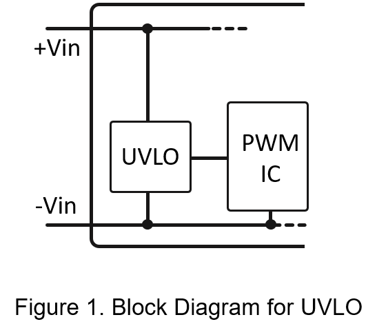
The main function of the UVLO circuit is to protect the internal components of the converter to avoid operating at a too low input voltage, causing high input current to damage the PWM IC or MOSFET. Or causing the output abnormal, such as low or discontinuous output voltage.
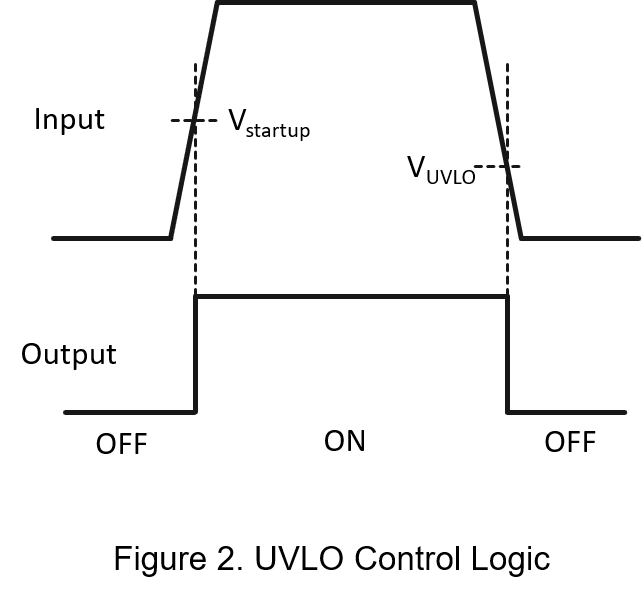
The control logic of the UVLO is that when the input voltage is higher than the minimum start up voltage, the converter will start up normally. When the input voltage is lower than the maximum shut down voltage, the converter will shut down.
2. Application
Table 1 shows the under voltage lock out specification. As Figure shows, when the input voltage is 8V or lower, the converter status is off. When the input voltage is 9V or higher, the status of the converter is on. When the input voltage is between 8V and 9V, the converter is in an undefined state. It is recommended not to operate the converter in this voltage range.
| Parameter | Condition | Min. | Type. | Max. | Unit. |
| Start-Up Voltage (0-100%) | Nominal 24V | 9 | Vdc | ||
| Under Voltage Lock-Out (0-100%) | Nominal 24V | 8 | Vdc |
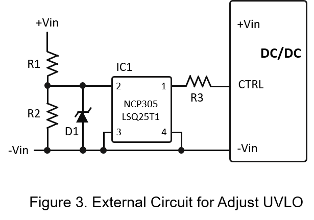
Figure 3 shows the external circuit for adjusting the UVLO. The control logic is the IC1 detects the input voltage through R1 and R2. When the input voltage is lower than the set value, IC1 pin1 is short circuited to -Vin, and the converter is turned off. When the input voltage is higher than the set value, IC1 pin1 will open, and the converter can operate normally.
3. Example
Next, it will show the test waveform of UVLO feature. And to adjust the UVLO voltage by external circuit. Table 2 shows the start up voltage and UVLO specification for four to one (9~36V) input range converter. As Table 2 shows, when the input voltage is higher than 9V, the converter can operate normally, and when the input voltage is lower than 8V, the converter is off.
| Parameter | Condition | Min. | Type. | Max. | Unit. |
| Start-Up Voltage (0-100%) | Nominal 24V | 9 | Vdc | ||
| Under Voltage Lock-Out (0-100%) | Nominal 24V | 8 | Vdc |
Figure 4 shows the test waveform, when the input voltage is higher than 8.8V, the converter operates normally. When the input voltage is lower than 8.3V, the converter is off. It can be seen from the test waveform that, the UVLO function working normally.
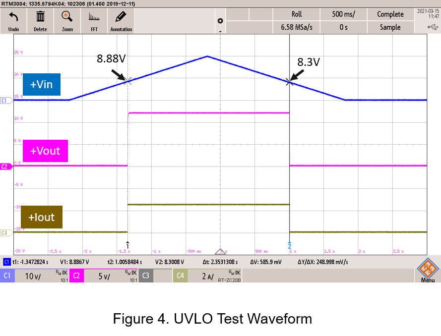
Figure 5 is the IC1 block diagram and specification. The control logic is when IC pin2 detects the set voltage, pin1 of IC1 will be opened, causing the CTRL pin of the converter to open. And the converter work normally.
The calculation formula for R1 and R2 as follows:
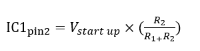
ICpin2 detects voltage for IC1.
Vstart up Start up voltage.
As Figure 5 shows, the detected voltage of IC1 is 2.346Vmax. And, the hysteresis voltage is 0.161. Therefore, the detection voltage should be set to 2.507V.
Assuming that the start up voltage is set to 20V, the R2 resistance is 100kΩ, and the After the formula, R1 can be calculated as 696 kΩ, and the closest resistance is 680 kΩ.
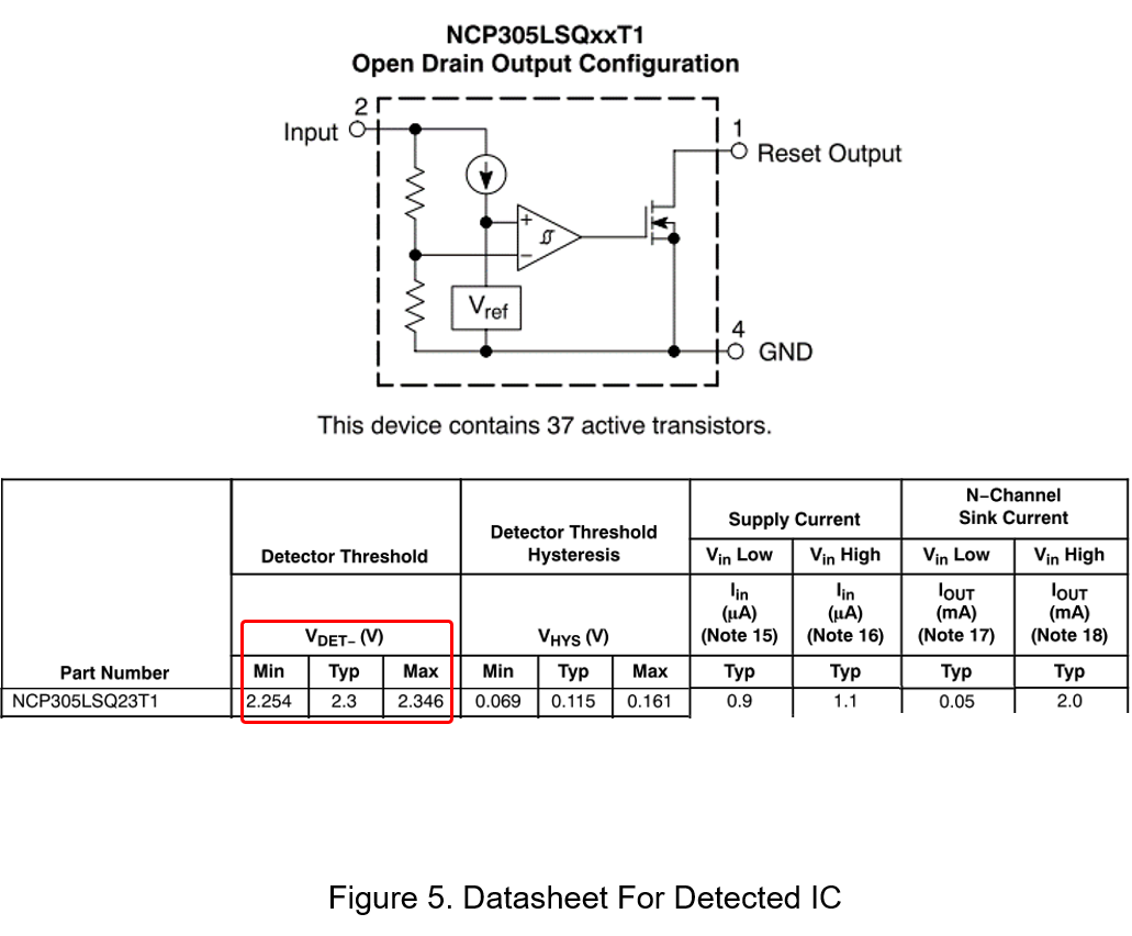
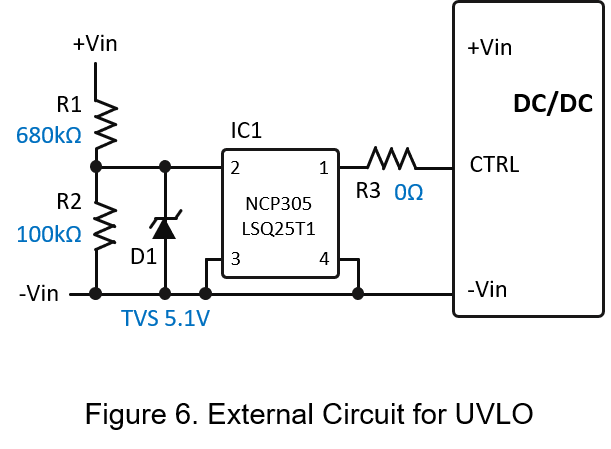
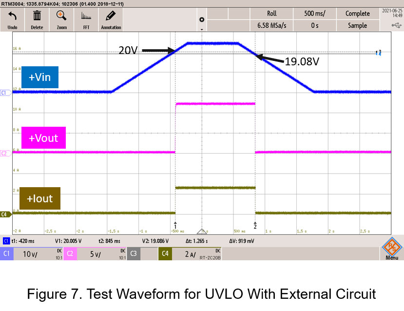
Figure 7 shows the test waveform. It can be seen from the figure that, when the input voltage is higher than 20V, the converter operates normally. When the input voltage is lower than 19.08V, the converter is off. Indicates that the external circuit can adjust the UVLO voltage of the converter.
Summary
The converter with UVLO function can protect the internal components from high int put current when the input voltage is low. Through the simple external circuit, the voltage of the input voltage latch can be adjusted, which is very suitable for battery applications or applications that need to adjust the cut-off voltage to meet the needs of battery protection or front-end power supply.
CTC is a professional service provider for high-end power supply modules (AC to DC Converter and DC to DC Converter) for critical applications worldwide since 30 years. Our core competence is to design and deliver products with leading technologies, competitive pricing, extremely flexible lead-time, global technical service and high-quality manufacturing (Made In Taiwan).
CTC is the only corporation certificated with ISO-9001, IATF-16949, ISO22613(IRIS), and ESD/ANSI-2020. We can 100% ensure not only the product, but also our workflow and service to match quality management system for every high-end application from the very beginning. From design to manufacturing and technical support, every single detail is operated under highest standard.