

You are here
Back to topHow to evaluate the heat dissipation of a power converter ?
The specifications of power converters usually define a derating curve. The reason is that the power converter has a maximum temperature limit. In order to make the converter operate in a safe temperature range, there is an upper load limit. If the power converter operates at full power, efficiency will need to improve, and the problem of temperature rise will need to solve. This article introduces the heat transfer method, calculates the thermal resistance from the temperature change and energy loss, and evaluates the heat dissipation through the thermal resistance.
1. Efficiency and power dissipation
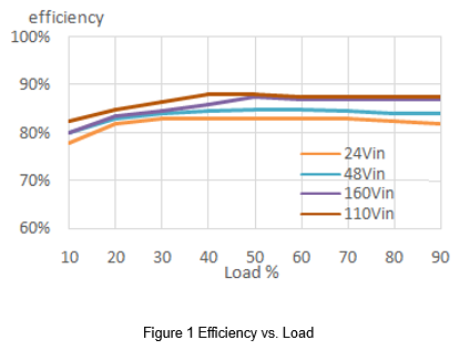
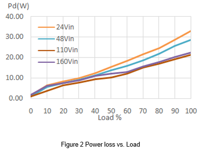
Efficiency is an important specification for evaluating power converters. It is defined as the percentage of output power divided by input power. When the input power is not equal to the output power, the difference is the lost energy. Power converters and electronic components will occur energy loss, most of which will turn into useless heat. Therefore, it is necessary to carefully deal with the problem of heat transfer to avoid damage to surrounding electronic components caused by high temperatures. Figure 1 shows the relationship between the converter's efficiency and the load, and Figure 2 shows the relationship between the converter's power loss and the load. These graphs show that a converter with more losses has lower efficiency.
2. Heat transfer
The common methods of removing heat for power converters include natural convection, heat sink, and cooling fan. Aluminum substrates are used to cover the products with high power. The reason is that the thermal conductivity of aluminum substrates is better than the plastic case, so more thermal energy can transmit through the aluminum substrates. If the external heat sink or a fan connects to the aluminum substrate, the removing heat capacity can effectively increase.
There are three ways of transferring heat energy: conduction, convection and radiation.
- Conduction
Conduction is the process by which heat energy is transmitted through collisions between neighboring atoms or molecules. Molecules in high-temperature objects have higher energy and the heat transfers from high temperature to low temperature. If the object is in contact with another with different temperatures, molecules will collision to produce energy transfer. The heat conduction capability is that solids are greater than fluids, and metal has the best heat conduction performance. Assuming that the heat transfer direction is the x-direction, Fourier's law simplifies as follows:
![]() (1)
(1)
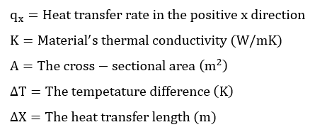
The heat transfer rate is proportional to the conductivity of the material, the cross-sectional area of the heat flow direction, and the temperature difference, and inversely proportional to the distance of heat transfer. Choosing a heat sink has to consider the material and thermal resistance, and let the contact area as large as possible. The closeness between the heat sink and the converter will also affect the effect of conduction. The uneven surface will cause a gap between the heat sink and the converter, and the air in the gap will greatly reduce the efficacy of thermal conduction. Therefore, thermal conductive glue or thermal pad can make the contact surface completely close to achieving the maximum effect.
- Convection
Thermal convection refers to the heat transfer phenomenon between a solid and a flowing fluid. It also includes the density difference between fluids, which will occur the mixing of fluids resulting in the heat transfer phenomenon. In the application of the converter, it can be divided into natural convection and forced convection. Natural convection is the convection that is naturally generated by the difference in air density when the heat on the converter transfer to the nearby lower temperature air. Forced convection is the use of a fan to force air convection.
The heat convection coefficient represents the effect of heat transfer. Factors affecting the heat convection coefficient include the temperature difference between the fluid and the solid, the velocity and direction of the fluid, and the shape and surface, and so on. The use of a fan can greatly reduce the thermal resistance from the surface of the converter to the air. However, it is necessary to pay attention to the direction of the radiating fins to allow the wind to circulate, and regularly replace the filter to avoid dust or foreign objects causing system failure.
- Radiation
Radiation does not need a medium and transmits in the form of waves. As long as the temperature of the object is more than absolute zero, it can continue to generate thermal radiation. At the same time, it also absorbs the thermal radiation released by the outside world. The benefit of heat radiation is closely related to the surface temperature. When the temperature is higher, the surface will have better emissivity. Therefore, if the converter is not the hottest object in the system, the heat dissipation may not increase but decrease. The surface emissivity is affected by the color, roughness, and material of the surface. Additionally, the heat has convert between itself and the surrounding objects, so it is both complicated and difficult to calculate the heat radiation. However, it is still possible to evaluate the layout of the converter in the system application based on the principle of heat radiation. The converter should avoid placing high-temperature parts nearby because the heat radiation of other parts will cause the temperature of the converter to rise, and also avoid placing near the temperature-sensitive element. Generally, the temperature of the converter during operation is higher than the outside, so the radiation still contributes to the overall heat dissipation.
3. Thermal resistance
Power converters or general electronic components need to evaluate for thermal effects. When the temperature is over the limit, the converter needs to be derated to avoid component damage. In this case, an appropriate thermal solution can be added, such as a heat sink or cooling fan. The benefit of the heat dissipation can be evaluated by the thermal resistance, but only considering the state of thermal equilibrium and not evaluating the non-linear temperature rise. Simple calculations can be used to understand the temperature change and select an appropriate heat sink.
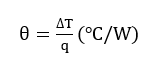
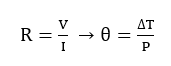
When the object is in contact with another with different temperatures, the heat will transfer from high to low. Therefore, two adjacent contact surfaces will produce a temperature difference DT, the heat transfer rate of the two contact surfaces is q, and the thermal resistance θ is defined as below.
 (2)
(2)
Thermal resistance is the ability of an object to resist heat transfer, so the greater the thermal resistance, the lower the thermal conductivity.
Electrical engineers can use it as an analogy with Ohm's law when doing calculations involving thermal resistance. Temperature difference replaces voltage, heat replaces current, and thermal resistance replaces resistance. Therefore, the model of Ohm's law can be equivalent to the calculation of thermal resistance.
 (3)
(3)
When calculating the thermal resistance of the converter, assuming that all the power dissipation by the converter converts into heat, the thermal conductivity q is the power loss of the converter.
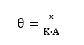
According to (1) and (2), the following equations can be obtained. The thermal resistance of the material can be calculated by the thermal conductivity of the material, the cross-sectional area of the heat flow direction and the distance of heat transfer.
 (4)
(4)
4. Temperature measurement
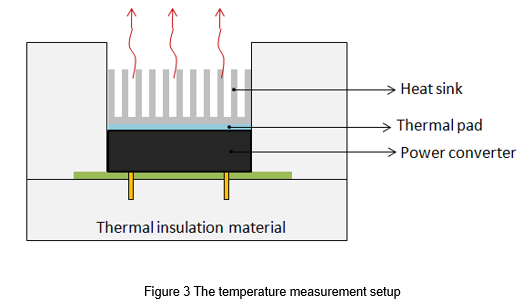
The power converter has a maximum operating temperature limit. If the temperature exceeds the upper limit, it may affect performance or cause irreversible damage. When evaluating the temperature, assuming a linear relationship between the heat dissipation path and the temperature, the measurement setup is to wrap the surrounding of the converter with a thermal insulation material, and the only opening is above the converter, as shown in Figure 3. The purpose is to make the heat dissipation direction all from the case surface to the air. In addition to the thermal camera can use to present the temperature simply and directly, and an electric thermocouple can also use to measure the case temperature and the ambient temperature.
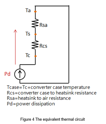
The equivalent thermal circuit shows in Figure 4. The total is the sum of thermal resistance on the heat dissipation path. The converter case to air resistance can calculate by the known power loss, and case temperature and the ambient temperature are measured.
![]() (5)
(5)
![]() (6)
(6)
After knowing the thermal resistance, the maximum temperature limit of the converter can be used to calculate the maximum operating ambient temperature. If the ambient temperature rises, the user also can calculate thermal resistance to estimate the appropriate heat sink or cooling fan.
It should be noted that the calculation results of the above methods contain margins. Especially the measurement of the ambient temperature, Ta, is very difficult. There is no unified measurement method currently. The distance between the measuring point and the converter will cause a great difference in the temperature. And in a forced convection environment, there is no conclusion on where Ta should be measured. Therefore, the accuracy depends on the measurement method and how many calculation conditions.
5. Thermal resistance calculation
5.1 Heat sink
Most of the heat of the converter will transfer from the aluminum substrate. Therefore, the heat sink should place on the aluminum substrate through a thermal pad. If the converter case to air resistance is decreased, the ambient temperature can increase when the converter is operating.
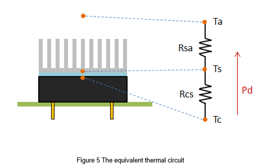
The equivalent thermal circuit is shown in Figure 5. The total thermal resistance Rca from the converter case to the air includes the converter case to the heat sink resistance, Rcs, and the heat sink to the air resistance, Rsa.
Example:
The power loss of a power converter is 17W, and the maximum temperature is limited to 110℃. Find the maximum operating ambient temperature after installing the heat sink.
The specifications of the heat sink and thermal pad are defined as follows:
Heatsink thermal resistance=3.2 W/℃
Thermal pad conductivity=1.56 W/m℃
Thermal pad Thickness =0.5mm
Surface area =57.9x36.8mm
The equivalent thermal circuit is shown in Figure 5, first calculate the thermal resistance of the thermal pad by formula (4).
 (7)
(7)
The total is the sum of thermal resistance on the heat dissipation path.
![]() (8)
(8)
Then calculate the maximum ambient temperature by formula (6)
![]() (9)
(9)
5.2 Cooling fan
The cooling fan gives forced convection. It must note that the filter should be replaced regularly to prevent dust from entering the chassis, which may reduce the cooling efficiency or cause the system to shut down. Placing heat sink should consider the relative position of wind direction and fins, and make the most efficiency to take away the heat.
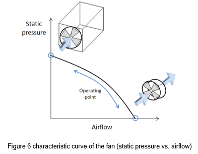
The characteristic of the fan is expressed by the airflow vs. static pressure, as shown in Figure 6. The maximum airflow means that the static pressure is zero and there is nothing around the fan. The maximum static pressure means that the device has no air outlet vent, air cannot escape, and the fan cannot propel the airflow. When the fan operates in different systems, the operating point will also change, which means that the airflow and static pressure will vary with the system. The airflow at the operating point can be calculated by the simulator or measured.
Example:
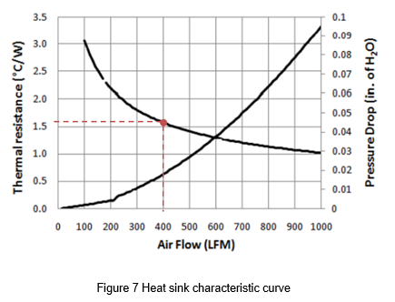
The power loss of a power converter is 17W, and the maximum temperature is limited to 110°C. The specifications of the heat sink are as shown in Figure 7. How much the airflow needs to give to the system if the ambient temperature rises to 80°C?
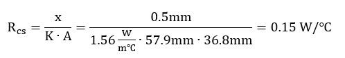
Thermal pad thermal resistance=0.15 W/℃
Calculate the thermal resistance from the heat sink to the air from the known temperature and power loss:
![]() (10)
(10)
1.6 W/℃ is the thermal resistance that needs to be achieved by the heat sink with the airflow. Generally, the specifications of the heat sink will attach by a graph with airflow vs. thermal resistance. According to the graph, the thermal resistance corresponds to the airflow of approximately 400LFM.
6. Summary
Appropriate heat dissipation methods are necessary for the power converter. To ensure that the power converter works at a safe temperature, a good heat dissipation method can increase the power and obtain great benefits. The thermal resistance equivalent model is used to analyze the thermal resistance between different materials. It can be used to evaluate the thermal transfer included the heat sink and cooling fan. Using a fan should consider the airflow change with thermal resistance. Also, note that the thermal resistance of the thermal pad for the contact surface between the heat sink and the converter is not negligible. In conclusion, the complex thermal performance can evaluate with simple calculation methods with the concept of thermal resistance.
CTC is a professional service provider for high-end power supply modules (AC to DC Converter and DC to DC Converter) for critical applications worldwide since 30 years. Our core competence is to design and deliver products with leading technologies, competitive pricing, extremely flexible lead-time, global technical service and high-quality manufacturing (Made In Taiwan).
CTC is the only corporation certificated with ISO-9001, IATF-16949, ISO22613(IRIS), and ESD/ANSI-2020. We can 100% ensure not only the product, but also our workflow and service to match quality management system for every high-end application from the very beginning. From design to manufacturing and technical support, every single detail is operated under highest standard.