

You are here
Back to topInsulation Specification in Railway
The electronic equipment used in railways is in a mobile, harsh environment and has many uncontrolled situations. Therefore, the well-known railway standard EN50155 defines conditions such as voltage changes and environmental endurance. Besides, there are several international standards for railway products, such as fire protection, shock and vibration, EMC, and so on. And the insulation is defined in EN50124 which mentions the minimum clearance and creepage distance between two conductors in electronic products. And this standard considers factors such as environmental conditions and material characteristics to decide the distance to protect users and train safety. This article will introduce EN 50124 defines the clearance and creepage and the factors affecting. Generally, different products have different insulation purposes. And discuss how the power converter meets the reinforced insulation.
1. EN 50124 scope
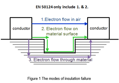
EN 50124 specifies the insulation requirements of railways are including equipment used in the three categories of signaling, rolling stock, and fixed installations, and used in areas where the altitude does not exceed 2000 meters. The scope in EN 50124 can be described from the mode of insulation failure. Due to the leakage current between two conductors cause insulation failure. There are three failure modes, as shown in Figure 1. The first is electron flows in the air. Secondly, one electron flows along the surface of the insulating material, and the last electron flow through the material. Since EN 50124 does not include solid and liquid insulation, only the clearance and creepage need to be considered. In addition, the distances through gases other than air and non-atmospheric pressure and equipment used under extreme conditions are not within the specification.
2. Important factor in determining distance
2.1 Voltage definitions
- Nominal voltage, Un:
A suitable voltage value used to designate or identify a given supply system
- Rated insulation voltage, UNm:
The root-mean-square withstand voltage assigned by the manufacturer to the equipment or a part of it, means that the insulation has the withstand voltage capability for permanent (over five minutes)
- Rated impulse voltage, UNi:
The impulse voltage value assigned by the manufacturer to the equipment or a part of it, indicates the withstand capability of the insulation against transient overvoltage
2.2 Insulation type
Insulation type can be defined as standards for five different purposes:
1. Basic insulation
Single-layer insulation can provide users with basic protection against electric shock.
2. Double insulation
Double insulation includes both basic insulation and supplementary insulation.
3. Functional insulation
The necessary insulation between the conductive parts in the equipment so that the equipment can operate normally so is not a safety consideration for users.
4. Reinforced insulation
A single-layer insulation system can reach the level of protection against electric shock equivalent to double insulation.
5. Supplementary insulation
The second layer of insulation independent of the basic insulation can protect the user from dangerous voltage when the basic insulation fails.
2.3 Pollution degree (PD)
EN 50124 defines the pollution degree of products in the operating environment, as shown in Figure 2. The PD is divided into the following different pollution levels. The PD1 to PD3 are also mentioned in IEC 62368, but the detailed classes of PD3A, PD4, PD4A, and PD4B are presented in EN 50124 because the environment in railway applications is more stringent. Insulation will be affected by the micro-environment. Tiny dust and moisture condensation may make insulation protection measures ineffective. Therefore, effective enclosures or sealing methods can reduce pollution degree.
| Dust Deposit | Humidity | |
| PD1 |
- no pollution - non-conductive - well protected |
- dry - no condensation |
| PD2 |
- non-conductive - protected - temporary conductivity caused by condensation |
- rare, short temporary condensation
|
| PD3 | - low conductivity (caused by condenstation) |
- frequent condensation |
| PD3A | - low conductivity |
- damp - long time condensation |
| PD4 | - occasionally conductive with periodic cleaning |
-rain, snow, ice, fog |
| PD4A(1) | - occasionally conductive coming from heavy pollution |
-rain, snow, ice, fog |
| PD4B(2) | - occasionally conductive coming from very heavy pollution |
-rain, snow, ice, fog |
3. Insulation distance(clearance & creepage)
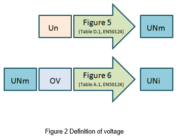
The insulation distance will change according to voltage, required insulation type, material group, PD, and overvoltage category. First of all, the power supply of the railway system is mostly a pantograph or third rail power supply system, or a battery system that stores energy to the train. Therefore, as shown in Figure 5, the nominal voltage of the equipment divides into three categories, DC, AC, and battery supply system, and they can correspond to the minimum UNm respectively. The UNi can be obtained from the UNm and overvoltage level (OV) through the table shows in Figure 6. Among them, OV and material groups are the factors that affect the insulation distance. For detailed definitions, please refer to "What is the insulation distance?"
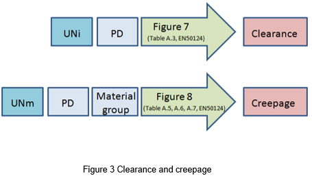
The minimum clearance should consider PD and UNi and can obtain from the table in figure 7. And the minimum creepage distance can be obtained by looking up the table. Besides the UNm and PD, there also think out the material group. The values in the table allow the use of interpolation to obtain more accurate values. If the creepage distance is insufficient, the groove or protrusion on the surface of the material can use to increase the distance.
| Nominal voltage Un | Minimun values of the rated Insulation voltage UNm | ||
| Power supply systems according to EN50163 | Battery supply systems | ||
|
d.c. kV |
a.c. kV |
V |
kV |
| 24/36 | 0.05 | ||
| 48/72 | 0.1 | ||
| 110/120 | 0.15 | ||
| 0.6 | 0.72 | ||
| 0.75 | 0.9 | ||
| 1.5 | 1.8 | ||
| 3.0 | 3.6 | ||
| 15 | 17.25 | ||
| 25 | 27.5 (36a/52a) | ||
|
Nominal voltage Un of the supply system (V) |
Rated Insulation voltage UNm a.c. or d.c. (V) |
Rated Impulse voltage UNi (KV) |
||||
| 3-phase | 1-phase | OV1 | OV2 | OV3 | OV4 | |
| up to 50 | 0.33 | 0.5 | 0.8 | 1.5 | ||
| up to 100 | 0.5 | 0.8 | 1.5 | 2.5 | ||
| 120 to 240 | up to 150 | 0.8 | 1.5 | 2.5 | 4.0 | |
| 230/400 277/480 | up to 300 | 1.5 | 2.5 | 4.0 | 6.0 | |
| 400/690 | up to 600 | 2.5 | 4.0 | 6.0 | 8.0 | |
| 1000 | up to 1000 | 4.0 | 6.0 | 8.0 | 12.0 | |
|
UNi (kV) |
PD1
|
PD2
|
PD3
|
PD3A
|
PD4
|
PD4A
|
PD4B
|
| 0.33 | 0.01 | 0.20 | 0.80 | 1.60 | 5.50 | ||
| 0.5 | 0.04 | 0.20 | 0.80 | 1.60 | 5.50 | ||
| 0.8 | 0.10 | 0.20 | 0.80 | 1.60 | 5.50 | ||
| 1.5 | 0.50 | 0.50 | 0.80 | 1.60 | 5.50 | ||
| 2.5 | 1.50 | 1.50 | 1.50 | 1.60 | 5.50 | ||
| 3 | 2 | 5.5 | |||||
| 3.5 | 2.5 | 6.2 | |||||
| 4 | 3 | 7.0 | |||||
| 4.5 | 3.5 | 8.0 | |||||
| 5 | 4 | 8.5 | |||||
| 6 | 5.5 | 10 | 18 | 20 | |||
| 8 | 8 | 14 | 21 | 23 | |||
| 10 | 11 | 18 | 23 | 26 | |||
| 12 | 14 | 22 | 27 | 30 | |||
| 15 | 18 | 27 | 33 | 37 | |||
| 18 | 22 | 32 | 39 | 43 | |||
| 20 | 25 | 36 | 43 | 48 | |||
| 25 | 32 | 45 | 53 | 58 | |||
| 30 | 40 | 54 | 63 | 68 | |||
| 40 | 60 | 72 | 82 | 87 | |||
| 50 | 75 | 91 | 101 | 106 | |||
|
UNm (V) |
PD1 | PD2 | PD3 | PD3A and PD4 | ||||||
| Material Groups I-II-IIIa-IIIb | Material Group | Material Group | Matrial Group | |||||||
| I | II | III | I | II | III | I | II | III | ||
| 10 | 0.080 | 0.40 | 1.0 | 1.6 | ||||||
| 12.5 | 0.090 | 0.42 | 1.05 | 1.6 | ||||||
| 16 | 0.100 | 0.45 | 1.1 | 1.6 | ||||||
| 20 | 0.110 | 0.48 | 1.2 | 1.6 | ||||||
| 25 | 0.125 | 0.50 | 1.25 | 1.7 | ||||||
| 32 | 0.140 | 0.53 | 1.3 | 1.8 | ||||||
| 40 | 0.16 | 0.56 | 0.8 | 1.1 | 1.4 | 1.6 | 1.8 | 1.9 | 2.4 | 3.0 |
| 50 | 0.18 | 0.6 | 0.85 | 1.2 | 1.5 | 1.7 | 1.9 | 2.0 | 2.5 | 3.2 |
| 63 | 0.2 | 0.63 | 0.9 | 1.25 | 1.6 | 1.8 | 2.0 | 2.1 | 2.6 | 3.4 |
| 80 | 0.22 | 0.67 | 0.95 | 1.3 | 1.7 | 1.9 | 2.1 | 2.2 | 2.8 | 3.6 |
| 100 | 0.25 | 0.71 | 1.0 | 1.4 | 1.8 | 2.0 | 2.2 | 2.5 | 3.2 | 4.0 |
| 125 | 0.28 | 0.75 | 1.05 | 1.5 | 1.9 | 2.1 | 2.4 | 2.5 | 3.2 | 4.0 |
| 160 | 0.32 | 0.8 | 1.1 | 1.6 | 2.0 | 2.2 | 2.5 | 3.2 | 4.0 | 5.0 |
| 200 | 0.42 | 1.0 | 1.4 | 2.0 | 2.5 | 2.8 | 3.2 | 4.0 | 5.0 | 6.3 |
| 250 | 0.56 | 1.25 | 1.8 | 2.5 | 3.2 | 3.6 | 4.0 | 5.0 | 6.3 | 8.0 |
| 320 | 0.75 | 1.6 | 2.2 | 3.2 | 4.0 | 4.5 | 5.0 | 6.3 | 8.0 | 10 |
| 400 | 1.0 | 2.0 | 2.8 | 4.0 | 5.0 | 5.6 | 6.3 | 8.0 | 10 | 12.5 |
| 500 | 1.3 | 2.5 | 3.6 | 5.0 | 6.3 | 7.1 | 8.0 | 10 | 12.5 | 16 |
| 630 | 1.8 | 3.2 | 4.5 | 6.3 | 8.0 | 9.0 | 10 | 12.5 | 16 | 20 |
| 800 | 2.4 | 4.0 | 5.6 | 8.0 | 10 | 11 | 12.5 | 16 | 20 | 25 |
| 1000 | 3.2 | 5.0 | 7.1 | 10 | 12.5 | 14 | 16 | 20 | 25 | 32 |
4. Tests and measurements of clearance & creepage
The clearance and creepage distance can judge by measurement, and the clearance can also use an electric test to verification of the requirements of the standard. But this method cannot be used to perform conventional insulation withstand voltage test. Notably, the creepage can only be confirmed by measurement, and cannot be replaced by voltage testing. The test voltage refers to table A.8 of EN 50124, and the test voltage value is corresponding to the clearance. The test method is as follows
- Impulse test: The 1,2/50μs impulse test voltage shall be applied three times for each polarity at intervals of 1 s minimum.
- Power-frequency test: The test frequency is 50 Hz ± 10% and The test value shall be reached in 5 s and be kept for 5 s.
- D.C. voltage test: The test value shall be reached in 5 s and be kept for 5 s.
5. How to achieve the reinforce insulation
The application of power products on railways will meet EN 50155, which includes requirements for operating temperature, voltage interruption, isolation voltage, and so on. In addition to EN 50155, the insulation distance requirements for railways are based on EN 50124, and the most stringent insulation type is reinforced insulation. If the power converter achieves the reinforce insulation, the insulation distance inside the power converter must be long enough to meet the requirements of reinforce insulation. In addition, the use of external systems as supplement insulation is also a method to be considered, but the converter should meet basic insulation at least. So the whole system formed the double insulation can be equivalent to reinforced insulation.
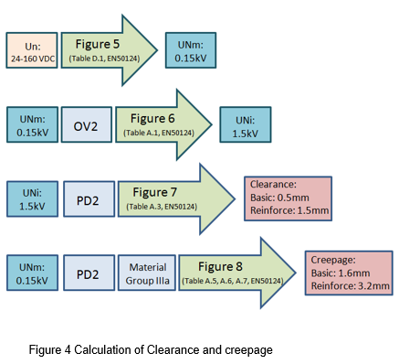
Because EN 50124 does not include solid and liquid insulation, the glue or other materials cannot use as an alternative to distance. To achieve the specified distance for reinforced insulation, moreover, there is a limit of volume. It will be a big challenge for power supply design. Therefore, if the power converter can cooperate with the system to achieve the double insulation of the entire system, it can meet the safety requirements and reduce the difficulty of design. Take a railway DC/DC power converter as an example, the input voltage range is 24-160VDC. The converter must reach the clearance and the creepage between the basic and reinforced insulation. The process is as follows:
5.1 Reinforce insulation
To achieve a power converter with a reinforced insulation level, it is necessary to confirm whether the distance between the primary and secondary sides of the power converter is sufficient. And a case is considered the overvoltage category is OV2, the pollution level is PD2, and the material level is III. The minimum requirement for the clearance of reinforced insulation is 1.5mm, and the creepage distance must reach 3.2mm, as shown in the figure 9.
5.2 Basic insulation + Supplement insulation
The minimum requirement of the clearance for basic insulation is 0.5mm, and the creepage distance is 1.6mm. Compared with the requirement of reinforced insulation, basic insulation can shorten the distance by about half. The supplement insulation by the external system can implement from circuit design or adding a protective casing. When the basic insulation fails, the supplement insulation can protect the user from electric shock. It formed a double insulation.
6. Summary
Since the development of railways has been more than a century, there are quite a lot of relevant international standards. EN 50124 is a specification for insulation distance and describes the definition of insulation distance in detail. In the design of power converters, the consideration of distance is very important. Especially in EN50124, other materials cannot be used as an alternative to insulation except distance. Although it increases the difficulty of the design, based on safety, these requirements are Don't allow to be despised.
CTC is a professional service provider for high-end power supply modules (AC to DC Converter and DC to DC Converter) for critical applications worldwide since 30 years. Our core competence is to design and deliver products with leading technologies, competitive pricing, extremely flexible lead-time, global technical service and high-quality manufacturing (Made In Taiwan).
CTC is the only corporation certificated with ISO-9001, IATF-16949, ISO22613(IRIS), and ESD/ANSI-2020. We can 100% ensure not only the product, but also our workflow and service to match quality management system for every high-end application from the very beginning. From design to manufacturing and technical support, every single detail is operated under highest standard.