

You are here
Back to topDemands of Power Supplies in Railway Applications
May 18, 2020
The development of the railway has more than a hundred years of history, and the driving capabilities and safety have been fully developed. Modern trains tend to add the functions of convenience and entertainment, such as information display screens, charging sockets, vending machines and so on. More and more additional equipment means that the power of the power converter must be increased, and under the limited space of the train, it must maintain the same volume or even shrink. Therefore, the power supply for railways with high power density will be a trend.
Europe was the first region to develop railways, so the international standards related to railways have also been perfected. Due to the long-term exposure of trains, they must face harsh environments, such as temperature changes, dust and vibration, and voltage fluctuations and transients of electrical equipment. Therefore, EN50155, the most commonly used specification in Europe, not only lists the working condition of electrical equipment and the voltage range of power supplies, but also the conditions of reliability. In addition, the standard RIA12 used in the United Kingdom emphasizes the specifications of transient and surge effects. The following lists the important features of CTC railway products, and are also a special point of the EN50155 specification.
- Operating temperature range
In terms of temperature requirements, there is divided into 6 levels, as shown in Table 1. If it is equipment in the cab or passenger cabin, it must meet the temperature specifications of OT1 or OT2. If it is a part used in the equipment, it must meet the OT3 or OT4 specifications. OT5 or OT6 can be used for Semiconductor Drive Unit or combustion engine control unit. It can't be used as a general specification for vehicle requirement. The railway products designed by CTC all meet the temperature requirements of OT4. Low temperature operation can reach -40°C, and high temperature can exceed the standard by more than 100°C.
| Class | Equipment operating temperature range (°C) |
| OT1 | -25 to +55 |
| OT2 | -40 to +55 |
| OT3 | -25 to +70 |
| OT4 | -40 to +70 |
| OT5 | -25 to +85 |
| OT6 | -40 to +85 |
- Variations of voltage supply
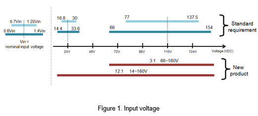
Since the power supply of the circuit system on the train may be affected, EN50155 defines two states respectively. In the steady state, the voltage fluctuation will be between 0.7*Vin and 1.25*Vin. In the transient state, the voltage fluctuation will be between 0.6*Vin and 1.4*Vin the standard voltage. During these voltage changes, functional deviation and damage cannot be caused.
Taking the commonly used input voltages of 24 VDC and 110 VDC as examples, the voltage fluctuations in the transient state are the largest, from 0.6*Vin to 1.4*Vin. As shown in Figure 1, when the input voltage is 24VDC, the voltage range must include 14.4 ~ 33.6VDC. When the input voltage is 110VDC, the voltage range must include 66 ~ 154VDC. In order to meet the requirements of EN50155, the power converter needs to have a wide input voltage range. For example, the 3: 1 input range product of CTC can cover the voltage change required by 110V, and the 12: 1 input range products can also meet from 24V to 110V full range of needs.
- Interruptions of voltage supply
Voltage drop or short-term power failure are also inevitable. Therefore, EN50155 has defined power supply voltage interruption class, which is divided into S1, S2 and S3. The most stringent one is S3. When the input voltage drops to 0V for 20ms, the output voltage must remain stable and cannot cause equipment failure.
In addition, the output voltage changes during power supply change over. When the input voltage drops to 0.6*Vin, the output voltage remains stable, which meet class C1. When the input voltage drops to 0V and returns to normal after 30mS, the output voltage remains stable in this process, it meets class C2.
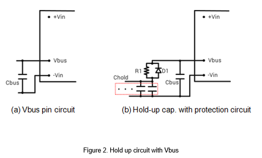
This specification usually needs to be achieved by an external capacitor. If it is a product with a Vbus pin, the capacitor (Cbus) between Vbus and -Vin is necessary, as shown in Figure 2- (a). During the transition of different power source, the electric power on the train becomes unstable in a short time, such as a sudden voltage drop or a short-term power failure. The protection circuit is suitable for this situation, as shown in Figure 2- (b). Parallel the diode (D1) and the resistor (R1), and then in series with Chold. According to the datasheet, choosing different capacitance of Chold can maintain hold up time for 10~30ms.
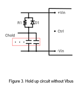
In addition, for products without Vbus pin, the hold up circuit must be connected between +Vin and -Vin, as shown in Figure 3. According to the datasheet, choosing different capacitance of Chold can maintain hold up time for 10~30ms.
- Isolated voltage
EN50155 divided the input voltage into three levels for the isolation withstand voltage, and maintained at the specified level for 1 minute, as shown in Table 2. CTC's railway products have isolation voltage up to 3000VAC, which is the highest isolation voltage level in the specification.
| Nominal input | Withstand Voltage |
| Vin<72VDC | 500 VAC |
| 72 VDC≦Vin<125 VDC | 1000 VAC |
| 125VDC≦Vin<315 VDC | 1500 VAC |
- EMC
The EMC requirements refer to Table 3 and are based on IEC 61000 specifications. ESD is a human body discharge mode that requires contact discharge ± 6KV and air discharge ±8kV. Fast transient requires ±2kV. Surge requires ±1kV line-to-line and ±2kV line-to-ground.
| Test Item | Criterion | Test Condition |
| ESD | IEC 61000-4-2 | Contact discharge±6kV Air discharge±8kV |
| Fast Transient | IEC 61000-4-4 | ±2kV, 5/50nS, 5kHz |
| Surge | IEC 61000-4-5 | 1.2/50uS ±2kV Line to Ground ±1kV Line to Line |
Application
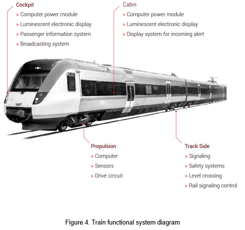
As shown in Figure 4, the train is divided into four parts, the cockpit, passenger cabin, propulsion and track side. First, in order to ensure the normal operation of train traction, braking and other systems, the propulsion system includes drive circuits, computer, and cooling fans. And for a comfortable riding environment, the cabin is equipped with lighting systems, display systems for incoming alert, air conditioning and other electronic equipment, which is also indispensable for modern railway train. The main control equipment is located in the cockpit, and the ECU is the main control terminal provides door control, broadcasting, and safety monitoring equipment. Finally, there are signal control systems and safety systems on the track side, which are used to provide correct signals to the driver and the commander to ensure that driving safely.
The DC power system on the train is mainly 24VDC and 110VDC, and the voltage is provided to each system through an isolated power converter.
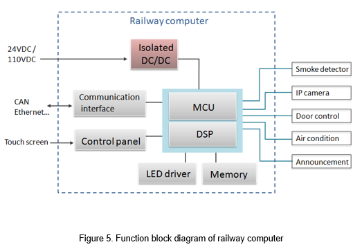
The following figure 5 is a block diagram of the railway computer application. The DC system on the train provides 24VDC or 110VDC to the railway computer, and converts to the voltage required by the MCU through by the isolated DC/DC converter. The internal composition included MCU, DSP, communication interface, memory and other functional modules. The computer system is the control core of the entire train, which can control electrical equipments such as smoke detector, IP cameras, door control, air conditioning, and broadcasters in each cabin.
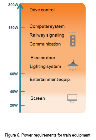
For various equipments on the train, there are different power requirements, and the power distribution of the equipments is roughly as shown in Figure 6. Drive control and power control require a lot of energy to drive, generally 200 ~ 300W. The computer and the railway signaling system are the main cores of the train, and the power is 150W or higher. Auxiliary electric doors and lighting equipment are powered by the auxiliary power supply on the train, and there are also communication equipment such as emergency intercom, monitors and broadcasts, etc., which is powered by the vehicle, and using the DC/DC converter converted to the require voltage. The power is usually 70~150W. Entertainment equipment and screens are additional equipments, using low and medium power 20~ 60W.
CTC is a professional service provider for high-end power supply modules (AC to DC Converter and DC to DC Converter) for critical applications worldwide since 30 years. Our core competence is to design and deliver products with leading technologies, competitive pricing, extremely flexible lead-time, global technical service and high-quality manufacturing (Made In Taiwan).
CTC is the only corporation certificated with ISO-9001, IATF-16949, ISO22613(IRIS), and ESD/ANSI-2020. We can 100% ensure not only the product, but also our workflow and service to match quality management system for every high-end application from the very beginning. From design to manufacturing and technical support, every single detail is operated under highest standard.