

You are here
Back to topRailway Power Standard Introduction
For railway power system, the high voltage level AC or DC power is converted into standard voltage level for the railway system or battery management system. Standard voltage level for railway system are 24V, 28V, 36V, 48V, 72V, 96V and 110V.
And the common voltage levels are 24V, 72V or 110V. There are two situations will have a large voltage fluctuation on the system. One is, when the system's power equipment is turned on or off, the converter may be damaged by the large voltage fluctuation. The other one is, due to a short circuit on a DC supply distribution line and subsequent operation of fuse/circuit breakers, input voltage may reduce to 0V for a short period. In this regard, EN 50155 has special definition.
EN 50155 is the European standard for railway electrical equipment. Most countries will refer to this standard, China's railway standard TB/T3021 is an example. The British railway standard is the RIA series, for example, the RIA12 has strict requirements for voltage fluctuations. French standards are NF-F 48, NF-F-01-510 and NF-F67000. Germany is VDE 0435 and 19PFL.
Application Profile
In railway system, the method for supply power can be roughly divided into three types. First one is generator set to provide the electric energy to system load. Second is using pantograph collect the electric energy, and transfer to the system by static converter. The third one is through battery management system to provide energy to train system. During the transition of different power source, the electric power on the train become unstable in a short time. Such as a sudden voltage drop or a short-term power failure. The following items are the points that should be noted when selecting a converter in railway application.
- Input Voltage Range :
EN 50155 has a special definition, the normal input voltage must be steady-state input voltage of 0.7 to 1.25 times. In addition, the converter must also comply with transient voltage dips and dips in the range of 0.6 to 1.4 times the steady-state voltage for a short period as shown in Table 1.
For example, when the system normal input voltage is 24V and 48V. According to Table 1, the normal minimum input voltage of converter should be 16.8V, and the maximum input voltage is 60V. For the fluctuation voltage spec, the minimum input voltage of converter should be 14.4V. And the maximum input voltage is 67.2V.
| Nominal Input Voltage (Vin) | Continuous Voltage Range (0.7*Vin-1.25*Vin) | Fluctuation Voltage Range | |
| 0.6*Vin (0.1S) | 1.4*Vin (1S) | ||
| 24 | 16.8-30 | 14.4 | 33.6 |
| 28 | 19.6-35 | 16.8 | 39.2 |
| 36 | 25.2-45 | 21.6 | 50.4 |
| 48 | 33.6-60 | 28.8 | 67.2 |
| 72 | 50.4-90 | 43.2 | 100.8 |
| 96 | 67.2-120 | 57.6 | 134.4 |
| 110 | 77-137.5 | 66 | 154 |
BS railway standards RIA12 general specification of traction & rolling stock electronic equipment from transients and surge in DC control systems. RIA12 requires that the electronic equipment must be able to withstand up to 3.5 times input voltage for 20mS duration as shown in Table 2.
| Voltage Level | Duration | |
| Brownout Voltage | 0.6*Vin | 100mS |
| Transient Voltage | 1.5*Vin | 1S |
| 3.5*Vin | 20mS | |
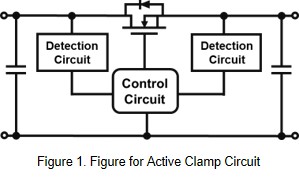
In general, use an active clamp circuit to meet the transient voltage requirements of RIA-12. External circuit limits the transient voltage to converter can withstand, as shown in Figure 1.
The control IC detects the input voltage, when the input voltage exceeds the clamp voltage. The control IC operate mosfet to limit the input voltage at the highest allowable input voltage of the converter. If only the TVS component is used to clamp the input voltage that will damage easily.
- Operating Temperature Range :
Environmental operating temperature levels for electronic equipment are listed in the EN 50155 as shown in Table 3. Temperature classes OT1 and OT2 should be used for passenger compartments and driver’s cab.
OT3 and OT4 should be used for equipment in technical cabinet.
OT5 and OT6 can be used for Semiconductor Drive Unit or combustion engine control unit. It can't be used as a general specification for vehicle requirement.
| Class | Equipment operating temperature range (°C) |
| OT1 | -25 to +55 |
| OT2 | -40 to +55 |
| OT3 | -25 to +70 |
| OT4 | -40 to +70 |
| OT5 | -25 to +85 |
| OT6 | -40 to +85 |
- Input Voltage Interruption and Change-Over
During the transition of different power source, the electric power on the train become unstable in a short time. Such as a sudden voltage drop or a short-term power failure.
Table 4 shows the test criteria of EN50155 when the input voltage interruption. Due to fault or short circuit conditions on the power supply distribution. And subsequent operation of fuse or circuit breakers, the input voltage may reduce to 0V for a short period.
The converter shall operate as specified after the voltage interruption, it can meet the specification of S1. When the input voltage drops to 0V and returns to normal after 10mS, the output voltage remains stable. In this condition, it meets the specifications of S2. In addition, the input voltage drops to 0V for up to 20mS, and if the output voltage remains stable, it meets the specifications of S3.
| Class | Requirements |
| S1 | In case of voltage interruption, no performance criterion is requested but the equipment shall continue to operate as specified after the voltage interruption. |
| S2 | In case of voltage interruption up to 10 ms, the equipment shall behave according to performance criterion A. |
| S3 | In case of voltage interruption up to 20 ms, the equipment shall behave according to performance criterion A. |
Table 5 shows the specifications for output voltage variation during power supply change-over. When the input voltage drops to 0.6 times the steady-state input, the output voltage remains stable, then it meets C1. When the input voltage drops to 0V and returns to normal situation after 30mS, the output voltage remains stable. In this condition, it meets the specifications of C2.
| Class | Requirements |
| C1 | At 0.6*Vin duration 100 ms (without interruptions). Performance criterion A |
| C2 | During a supply break of 30 ms stating at Vin. Performance criterion B |
In order to meet the requirements of S2, S3 and C2. Adding additional energy storage is required at the input side of any DC/DC converter. The most common way is to connect an external capacitor at the input. And the value of capacitor can be calculate by the following formula :
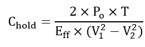
Po : Converter Output Power
T : Maintenance Time
Eff : Efficiency of Converter
V1 : Normal input voltage
V2 : Converter Lock-out Voltage
For example, the converter has an output power of 40W and an efficiency of 90%. The normal voltage is 110V, the lock-out voltage is 38V, and the expected maintenance time is 20mS. According to the formula, the capacitance value is 166.8uF. Which means, if the converter want to meet the maintenance time of 20mS. It needs to add more than 166.8uF capacitor at the input.
- EMS
The EMI requirements for railway electrical equipment can be referred to EN 55011, which have corresponding specifications for conducted and radiated interference. Table 6 shown the EMC requirement can be refer to the IEC 61000. The test condition of ESD is contact ±6Kv and air ±8kV at HBM. Fast transient is ±2kV. Surge is line-to-line ±1kV and line-to-ground ±2kV.
| Test Item | Criterion | Test Condition |
| ESD | IEC 61000-4-2 | Contact discharge ±6kV Air discharge ±8kV |
| Fast transient | IEC 61000-4-4 | ±2kV, 5/50nS, 5kHz |
| Surge | iec 61000-4-5 | 1.2/50 uS ±2kV Lint to Ground ±1kV Line to Line |
- Reliability Test
The electronic equipment on the train must be able to withstand the vibration and shock in normal operation, and must be able to operate normally under various environment situation.
Test requirements for vibration and shock are described in EN 61373, as shown in Table 7. There are A and B types for vibration test, and Class A refers to parts, equipment or parts that are directly mounted on the train. Class B refers to parts that are installed in equipment that is placed on or under the train.
| Test Item | Criterion | Category | Test Condition (m/s2) |
| Vibration | Function Random | Class A | V : 0.75, T : 0.37, L : 0.5 |
| Class B | V : 1.01, T : 0.45, L : 0.7 | ||
| Simulated long-life | Class A | V : 4.25, T : 2.09, L : 2.83 | |
| Class B | V : 5.72, T : 2.55, L : 3.96 | ||
| Shock | Class A/B | V : 30, T : 30, L : 50 | |
| Test Item | Criterion |
| Temperature Cycling | MIL-STD 202G |
| Power Thermal Cycling | MIL-STD 202G |
| Cold | EN 60068-2-1: 2009 |
| Dry Heat | EN 60068-2-2: 2009 |
| Damp Heat | EN 60068-2-3: 2010 |
- Reverse Polarity Protection
If the converter input is reversed, it will not only damage to the converter, but also short circuit the system power. To ensure the installers cannot reverse connect the power to any equipment, some safeguards must be taken. For example, a fool-proofing mechanism can be designed on the input terminal. In addition, on the electrical surface, the anti-reverse diode can be connected in series with the input terminal to prevent the influence of polarity reversal. It can connect anti-reverse diode in series to prevent the influence.
Summary
There are many kinds of power source in railway application, and the system voltage variability is larger. Therefore, a converter with a wide operating voltage is critical in railway applications. For example, a converter with wide operating voltage, which can satisfy different voltages requirements. In addition, due to the harsh environment of the railway, some climates may snow or be very hot. Therefore, it is very important that the converter has good EMI, EMC and high reliability.
CTC is a professional service provider for high-end power supply modules (AC to DC Converter and DC to DC Converter) for critical applications worldwide since 30 years. Our core competence is to design and deliver products with leading technologies, competitive pricing, extremely flexible lead-time, global technical service and high-quality manufacturing (Made In Taiwan).
CTC is the only corporation certificated with ISO-9001, TS-16949, ISO22163 and ESD/ANSI-2020. We can 100% ensure not only the product, but also our workflow and service to match quality management system for every high-end application from the very beginning. From design to manufacturing and technical support, every single detail is operated under highest standard.