

You are here
Back to topIsolated gate driver selection guide
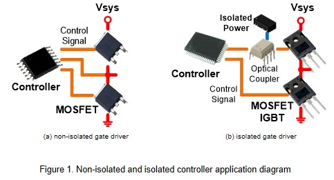
For a system with low operating voltage, switching component can directly connect to the controller, as long as the withstand voltage of the controller is within the allowable range, as shown in figure 1(a). When the system operating voltage is about hundreds or kilovolts, having galvanic isolation between the controller and switching component is essential. Using photocoupler and isolated power supply are the common method to have galvanic isolation, as shown in Figure 1(b).
The following items are the points that should be noted when selecting an isolated gate driver power supply.
- Output Voltage of Converter
The operating voltage of converter is determined by the specifications of the switching element, like MOSFET or IGBT. It must be confirmed that the converter output voltage does not exceed the maximum value of the gate voltage for switching elements. For example, if the switch is IGBT, generally a dual-output converter with output voltage of +15V, -8V will be used as the gate driver power source. If the switch is MOSFET, SiC or GaN, a single output power supply can be used.
- Output Power for Converter
The following formula shows how to decide the converter wattage.
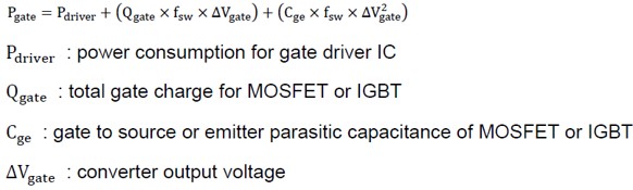

 Assume that the power requirement of the gate driver is 0.6W. The parameter of switch are Qgate = 1.65uC, Cge = 20nF, and the system operating frequency is 16kHz. The calculated result is 0.6W+0.792W+0.288W=1.68W. Which means it is recommended to use at least 2W converter.
- Isolation Capability
This item is determined by the operating voltage of the system. System operating voltage is proportional to Isolation Capability. The higher the system operating voltage, the higher converter isolation capability needed.
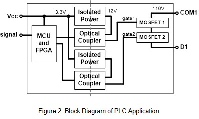
Figure2 shows the block diagram of PLC application. The input voltage is 3.3V, and the output terminal voltage is 110V. In this case, the working voltage between two ends of the system may reach 110V+3.3V.
In this application, the working voltage exceed the requirements of safe operating voltages, so it needs to use isolated converter. According to the specified insulation voltage, the isolation capability needs to be at least 2 times the operating voltage plus 2000V.
- Isolation Capacitance
Isolation capacitance is the parasitic capacitance between the converter input and output side. Through the following formula, it can be found that the isolation capacitance is proportional to the leakage current.
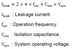
The power loss is proportional to leakage current. If the system needs to operate at high operating frequencies and high voltages, we need to pay more attention on the size of the insulation capacitor of the converter, to avoid too much temperature increasing.
- Short Circuit Protection
When the system switch has been damaged, the output of the converter may be short-circuited. In this case, the short circuit protection can avoid the damage of converter from malfunction of system
- CMTI
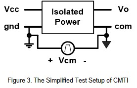
Common-Mode Transient Immunity (CMTI) is a crucial parameter of a gate driver power source, especially when system operating at high switching frequency. The unit is normally in kV/uS.
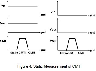
A simplified CMTI test setup is shown in Figure 3, and the typical common-mode pulse waveform are shown in Figure 4. CMTI is defining the capability of converter, and make sure if it can maintain a normal output when the common mode interference injects between the both sides of the isolated converter.
For example, CMTI defines whether the converter functions well within the datasheet specifications, when striking both side of the isolated converter with very high rise (positive) slew rate, or high fall (negative) slew rate.
Application Circuit
Figure 5 shows the diagram for bridge circuit of three phase inverter. Control signal drives the MOSFET through an isolated gate driver. Because that the high side MOSFET doesn't share the common ground, each high side MOSFET needs their own isolated power source. For the same reason, the low side MOSFET can use the same power source. In this case, it's necessary to check the total power consumption which the gate driver and MOSFET needed.
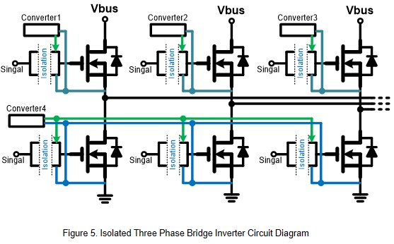
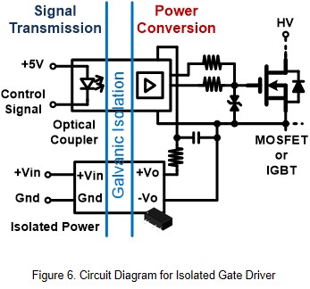
Figure 6 shows the circuit diagram for isolated gate driver. As the figure shows, control signal drives the MOSFET through optocoupler. The power to drive switching elements such as MOSFETs, IGBTs, or SiC is provided by an isolated power supply. In order to prevent the gate being damaged by electrical over-stress, it will connect TVS diode in parallel at gate and source.
Example
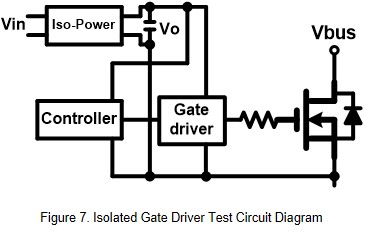
Here is a demo of gate driver circuit by using 2W converter with external circuit like figure 7.
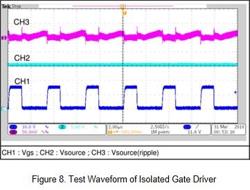
As figure 8 shows when the control signal drives the MOSFET, the converter output voltage variation and voltage ripple are very small.
Summary
Converter with high isolation voltage are commonly used in industrial and new energy fields, such as high operating voltage motor controller or solar inverter. Low isolation capacitor prevents the converter for additional power loss and heat at high operating voltage. The Short-Circuit Protection can protect the converter and the system when short circuit situation occurs in the system. Therefore, the high isolation voltage, low isolation capacity converter with SCP function are the critical feature for gate driver power.
CTC is a professional service provider for high-end power supply modules (AC to DC Converter and DC to DC Converter) for critical applications worldwide since 30 years. Our core competence is to design and deliver products with leading technologies, competitive pricing, extremely flexible lead-time, global technical service and high-quality manufacturing (Made In Taiwan).
CTC is the only corporation certificated with ISO-9001, TS-16949, ISO22163 and ESD/ANSI-2020. We can 100% ensure not only the product, but also our workflow and service to match quality management system for every high-end application from the very beginning. From design to manufacturing and technical support, every single detail is operated under highest standard.